AMX DX-RX-4K60 Handleiding
AMX Niet gecategoriseerd DX-RX-4K60
Bekijk gratis de handleiding van AMX DX-RX-4K60 (2 pagina’s), behorend tot de categorie Niet gecategoriseerd. Deze gids werd als nuttig beoordeeld door 101 mensen en kreeg gemiddeld 4.5 sterren uit 5 reviews. Heb je een vraag over AMX DX-RX-4K60 of wil je andere gebruikers van dit product iets vragen? Stel een vraag
Pagina 1/2
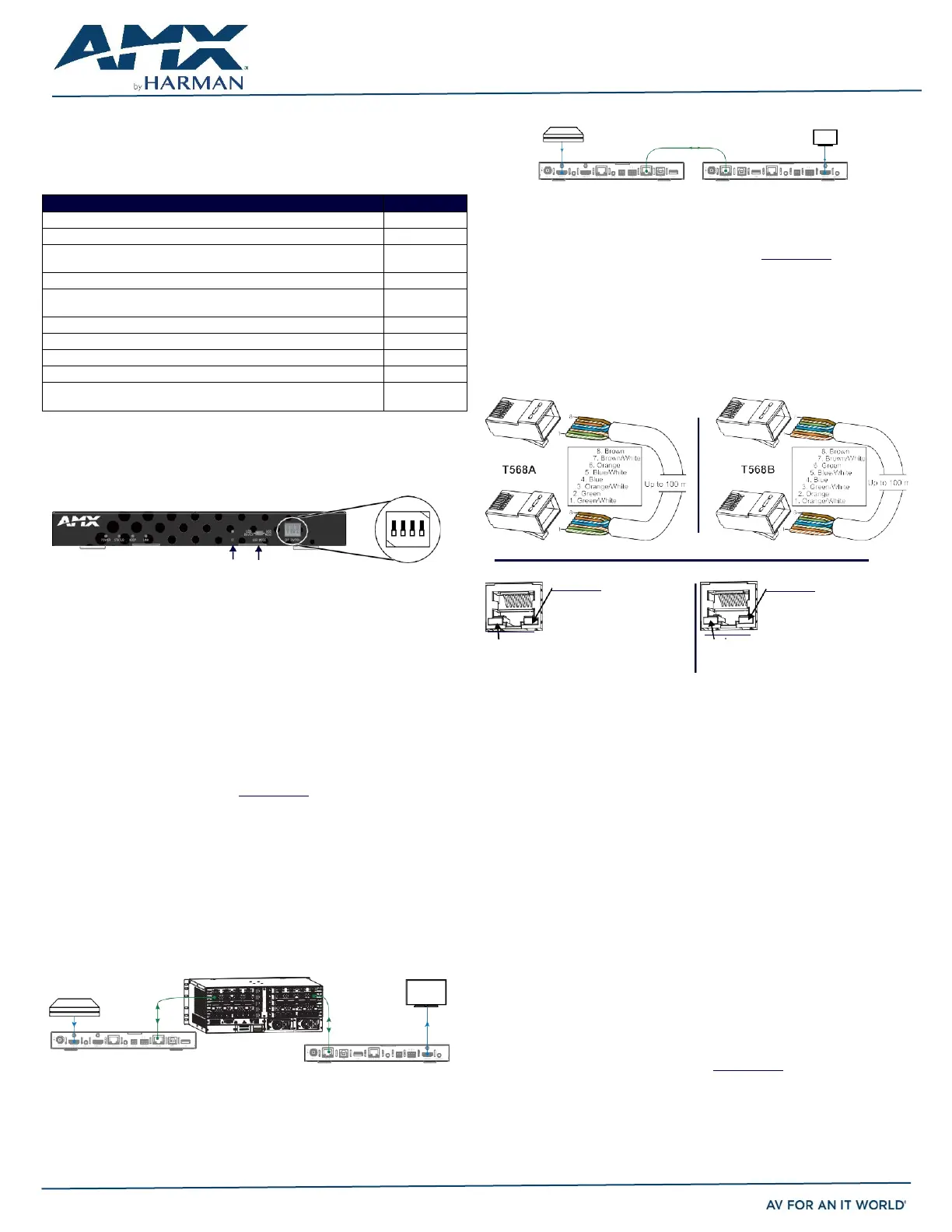
DIP Switch Toggles – Default OFF (for Auto-setup, see next page)
Before installingtheunits,findthescenarioyouareusinginthetablebelowandsetthe
DIP switchtogglesaccordingly.Toggle #4isreservedforfuture functionality.
For standalone pair upgrades, set Toggles #1-2-3 to ON and connect one unit to a
Controller.
COMMON SCENARIOS
TOGGLES
Standalone Setup
1 - 2 - 3
AV signals only (plus serial/IR passthrough)
OFF - OFF - OFF
AV with Ethernet passthrough to networked device (plus serial/IR
passthrough)*
ON - OFF - OFF
AV with NetLinx control of TX/RX unit and serial/IR ports**
ON - ON - ON
AV with NetLinx control of TX/RX unit and serial/IR ports, plus Ethernet
passthrough to network device*
ON - ON - ON
Switcher Setup (TX/RX with Enova DGX/DVX /DGX 100 Series Switcher)
1 - 2 - 3
AV signals only
OFF - OFF - OFF
AV with Ethernet passthrough to networked device*
ON - OFF - OFF
AV with NetLinx control of TX/RX unit and serial/IR ports
OFF - OFF - ON
AV with NetLinx control of TX/RX unit and serial/IR ports, plus Ethernet
passthrough to network device*
ON - OFF - ON
* Connect ICS LAN port of DXLink unit to network device (e.g., laptop, IP controlled
projector, ICSLan Device). In standalone setup, connect ICS LAN port of other DXLink
unit to network.
** In standalone setup using NetLinx control of DXLinkserial/IR ports, only one of the
DXLink units should be connected to network (the unit with #1 Toggle enabled).
SourceDevice
Destination Device
DXLINKTransmitter DXLINKReceiver
FIG. 3 DXLINK TX AND RX AS EXTENDER SOLUTION
Mounting Options (Rack Trays and Mounting Brackets)
FordetailsonthefourversatilemountingkitoptionsforV Stylemodules(racktray,rack
tray with fill plates, surface mount, and pole mount), seewww.amx.com
IMPORTANT: When mounting under a surface, the module should be mounted upright and
lowered in the mounting bracket slots to provide an airflow gap between the surface and
the vent holes. If not using V Style brackets, be sure to leave a gap between the top of
the unit and the surface for heat to escape.
Twisted Pair Cable Pinouts and RJ-45 LEDs
The DXLink and ICS LAN 10/100 ports both use twisted pair cable. FIG. 4 shows two
pinouts that can be used for either port. FIG. 5 shows the LEDs for each port.
FIG. 4 RJ-45 PINOUTS
FIG. 1
DIP SWITCH TOGGLES ENABLE/DISABLE SPECIAL FUNCTIONALITY
Overview
TheDX-TX-4K60andDX-RX-4K60 transmitHDMI, audio, USBandcontrolovertwisted
Yellow LED
On - Speed status is 100 Mbps
Off- Speed status is 10 Mbps
ICS LAN 10/100 Port
Green LED
Yellow LED
On - Authenticated HDCP
Flashing - Video active; no HDCP
Off- No Video
DXLink Port
pair cable. The TX also has an HDMI local loop out. DXLink Modules can be set up in
one of three ways:
•
EndpointMode(Switcher) – connectone or moretoa switcher with anintegrated
Controller.
•
EndpointMode(Standalone) – connect TX/RXpairdirectly to eachother with one
Green LED
On - Link status is active
Off- Link status is not active
FIG. 5 RJ-45 PORTS
On - Connection established
Off- Connection not established
connected to a NetLinx Central Controller via LAN or directly to Controller.
•
ExtenderMode(Standalone)– connect TX/RXpair directlyto eachother.
These Modules support InstaGate Pro® and SmartScale® Technology.
The Hardware Reference Manual – DXLink Twisted Pair 4K60 Transmitters/Receiver
contains complete documentation (including full specifications and supported input
and output resolutions); for details, see www.amx.com.
System Setup
The DX-TX-4K60 and DX-RX-4K60 work with a switcher that supports DXLink
Technology or as a stand-alone pair to transmit audio, video and control signals. The
Transmitter receives audio and video from the HDMI source and transmits both audio
andvideooverthe DXLinktwisted paircable. ThisDXlink cablecan beconnecteddirectly
to a DXLink Receiver or to a DXLink input on a DXLink switcher where it can be routed to
a DXLink output and connected to a DXLink Receiver. The DXLink Receiver converts the
DXLink input to HDMI and analog audio outputs. On the Transmitter, stereo audio
connections are provided as a supplemental audio input. Both the Transmitter and the
ReceiversupportRS-232 forserial data transfer,USB, IR, and Ethernet.
Destination Device
Attaching Signal, Transport, and Control Cables
Important Twisted Pair Cabling Requirements and Recommendations:
•
DXLinkcable runsrequire shielded categorycable(STP) of Cat 6 (orbetter).
•
Forcablerunslongerthan 70meters total,shielded category cable(STP) ofCat6A
or better isrequired.
•
DXLinktwisted paircable runsfor DXLinkequipmentshall onlyberun within
a commonbuilding.*
•
DXLink(RJ-45) connectorsmustnot beused for connectingto a standard
Ethernet Network. The connector is used for signaltransport.
•
Do not create a network (Ethernet) loop. A network loop is created when the
enclosureandoneormoreofits DXLinkModulesareconnectedto a commonLAN
(or a standalone pair when both endpoints connect to the samenetwork).
•
DXLinkdelivers10.2Gb/sthroughput overshieldedcategorycable.Basedonthis
bandwidth requirement, we recommend following industry standard practices
designed for 10 Gigabit Ethernet when designing and installing the cable
infrastructure.
•
The cables should be no longer than necessary to reach the end-points. We
recommendterminatingthecable totheactualdistancerequiredrather than
leaving any excess cable in a serviceloop.
Source Device
DXLINK Input Board
Cat x
DXLINK Output Board
•
Formoreinformation,seethe HardwareReference Manual – DXLinkTwistedPair
4K60Transmitters/Receiver.
HDMI IN
DXLINK Transmitter
Up to330ft
(100m)
D
C
F
L
T
LAN 100/1000
Cat x
Up to330ft
(100m)
DXLINK Receiver
HDMI OUT
* “Common building” is defined as: Where the walls of the structure(s) are physically
connected and the structure(s) share a single ground reference.
For more details and helpful cabling information, reference the white paper titled
“Cabling for Success with DXLink” available at www.amx.com
or contact your AMX
representative.
FIG. 2 DXLINK TX AND RX AS ENDPOINTS WITH COMPATIBLE DXLINK EQUIPMENT
Cat x Up to330ft(100m)
HDMI IN
HDMI OUT
ON
1 2 3 4
ID USB MODE
QUICK START GUIDE
DXLink™ Twisted Pair 4K60 Transmitter/Receiver
Product specificaties
| Merk: | AMX |
| Categorie: | Niet gecategoriseerd |
| Model: | DX-RX-4K60 |
Heb je hulp nodig?
Als je hulp nodig hebt met AMX DX-RX-4K60 stel dan hieronder een vraag en andere gebruikers zullen je antwoorden
Handleiding Niet gecategoriseerd AMX

10 Mei 2026
7 Mei 2026
5 Mei 2026
4 Mei 2026
24 November 2025
5 Augustus 2025
5 Augustus 2025
4 Augustus 2025
4 Augustus 2025
4 Augustus 2025
Handleiding Niet gecategoriseerd
Nieuwste handleidingen voor Niet gecategoriseerd
8 Juni 2026
8 Juni 2026
8 Juni 2026
8 Juni 2026
8 Juni 2026
8 Juni 2026
8 Juni 2026
8 Juni 2026
8 Juni 2026
8 Juni 2026