AMX AXB-REL8 Handleiding
AMX Controller AXB-REL8
Bekijk gratis de handleiding van AMX AXB-REL8 (2 pagina’s), behorend tot de categorie Controller. Deze gids werd als nuttig beoordeeld door 144 mensen en kreeg gemiddeld 5.0 sterren uit 7 reviews. Heb je een vraag over AMX AXB-REL8 of wil je andere gebruikers van dit product iets vragen? Stel een vraag
Pagina 1/2
Installation Guide
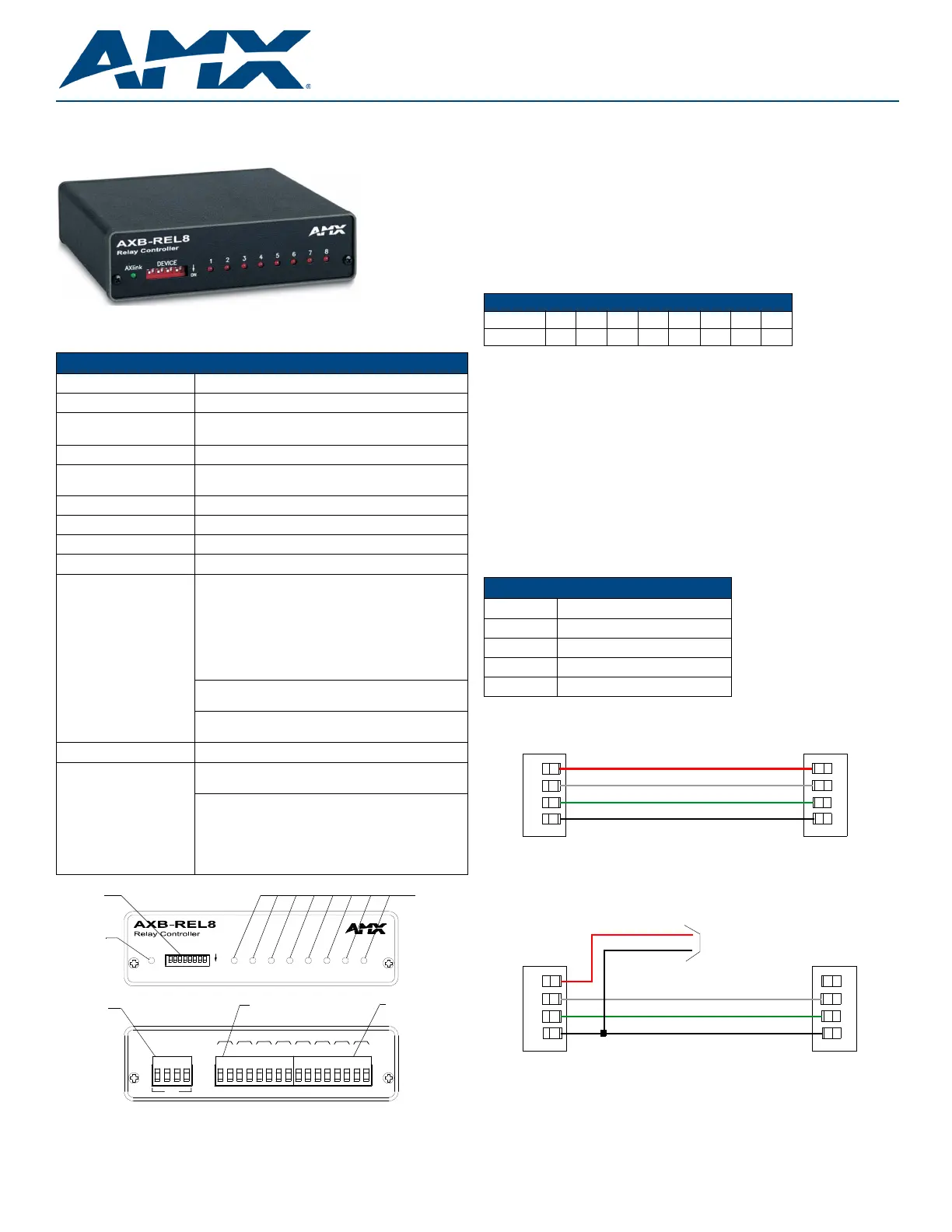
AXB-REL8 Relay Controller
Overview
The AXB-REL8 (FG5774) controls closure-activated devices, acting as an eight-channel
relay control port on the AxLink bus.
Specifications
Installation
Setting the DEVICE DIP Switch
Note: Use the DIPSwitch 2.0 application available for free download from AMX to quickly
figure out DIP Switch settings for all types of DIP Switches.
Set the device number on DEVICE DIP switch, located on the front of the AXB-REL8. The
device can be 1 of the 255 devices in an Axcess control system. The device number must
match the device assignment in the Axcess program. Device numbers are assigned into the
following three segments:
•Cards 1 through 95
•Boxes 96 through 127
•Panels 128 through 255
Set the device number by setting the device DIP switches. The device number is the total of
all of the switches in the ON position, and take effect by cycling the power.
Wiring
Preparing and Connecting Captive Wires
1.Strip 0.25 inch of wire insulation off all wires.
2.Insert each wire into the appropriate opening on the connector according to the wiring
diagrams and connector types described in this section.
3.Tighten the screws to secure the wires. Do not tighten the screws excessively; doing
so may strip the threads and damage the connector.
Wiring Guidelines
The interface requires a 12 VDC power to operate properly. The interface uses a PSN2.8
power supply. The Central Controller supplies power via the AxLink cable or external 12 VDC
power supply.
The maximum wiring distance between the Central Controller and interface is determined by
power consumption, supplied voltage, and the wire gauge used for the cable.
The table below lists wire sizes and maximum lengths allowable between the REL8 and
Central Controller. The maximum wiring lengths for using
AxLink power are based on a minimum of 13.5 volts available at the Central Controller’s
power supply.
AxLink Data and Power Connections
Connect the control system's AxLink connector to the AxLink connector on the rear panel of
the AXB-REL8 for data and 12 VDC power as shown in FIG.3.
Wiring AxLink With Optional 12 VDC Power Supply
Connect the control system's AxLink connector to the AxLink connector on the rear panel of
the AXB-REL8 as shown in FIG.4.
Use a 12 VDC power supply when the distance between the control system and AXB-REL8
exceeds the limits described in the Wiring Guidelines at 170 mAtable, or the power supply
current capacity cannot accommodate the 170 ma (max) draw of the AXB-REL8.
•Make sure to connect the GND and +12 VDC wire on the AXB-REL8 AxLink connector
end.
•Do not connect the optional +12 VDC power supply wire to the control system's power
supply side of the AxLink connector (FIG.4).
FIG. 1 AXB-REL8
Specifications
Dimensions (HWD)1.51" x 5.55" x 5.45" (3.84 cm x 14.10 cm x 13.84 cm)
EnclosureNon-glare, high-impact black matte plastic
Power Consumption•Baseline draw: 90 mA @ 12 VDC (min)
•With all 8 relays On: 170 mA @ 12 VDC (max)
Weight17.50 oz. (496.11 g)
Included AccessoriesMetal tab strips included for external adjacent relay com-
muning.
Optional AccessoriesAC-RK Accessory Rack Kit
Dimensions (HWD)1.51" x 5.55" x 5.45" (3.84 cm x 14.10 cm x 13.84 cm)
EnclosureNon-glare, high-impact black matte plastic
Front Panel Components
AxLink Status indicatorAxLink LED (green and blinks to indicate AxLink
communication activity and power:
•Full-Off indicates no power is being received or the
controller is not functioning properly.
•One blink per second indicates power is active and
AxLink communication is functioning.
•Full-On indicates there is no AxLink control or activity, but
power is On.
Device DIP switchAn eight-position DIP switch is used to set the device
number for the AXB-REL8.
Relay LEDs 1-8 (Red)Illuminate when associated relay is closed. Relay LED's
should match panel control function.
Rear Panel Components
AxLink connectorFour-pin captive wire receives power and information via
the AxLink bus and AxLink system controller.
Relay contactsEight (normally -open) isolated two-pin relay contacts
1 A @ 28 VAC or VDC:
•Relays 1-4 can share a common if use jumper "A" pins
with a tab strip
•Relays 5-8 use discrete commons (wire commons
individually)
FIG. 2 AXB-REL8 front and rear views
DEVICE
AXlink
ON
AXlink
AXM
GND
PWR
AXP
B
21345678
B
78
ABA
56
ABBB
4
ABA
2
3
ABA
1
A
Device DIP
switch
AxLink LED
AxLink
connector
Relay contacts 5-8
(discrete commons)
Relay contacts 1-4
(shared commons)
Relay
LEDs (1-8)
DEVICE DIP Switch Settings
Position
12345678
Value
1248163264128
Wiring Guidelines at 170 mA
Wire SizeMaximum Wiring Length
18 AWG690.42 feet (210.43 m)
20 AWG436.80 feet (133.13 m)
22 AWG272.33 feet (83.00 m)
24 AWG171.66 feet (52.32 m)
FIG. 3 AxLink wiring
FIG. 4 Wiring AxLink with Optional 12 VDC power supply
PWR +
AXP/TX
AXM/RX
GND -
PWR +
AXP/TX
AXM/RX
GND -
AXB-REL8Central Controller
PWR (+)
GND (-)
Local +12 VDC power supply
(coming from the PSN power supply)
PWR +
AXP/TX
AXM/RX
GND -
PWR +
AXP/TX
AXM/RX
GND -
AXB-REL8Central Controller
Product specificaties
| Merk: | AMX |
| Categorie: | Controller |
| Model: | AXB-REL8 |
Heb je hulp nodig?
Als je hulp nodig hebt met AMX AXB-REL8 stel dan hieronder een vraag en andere gebruikers zullen je antwoorden
Handleiding Controller AMX

19 November 2024
27 Februari 2024
27 Februari 2024
27 Februari 2024
2 Februari 2024
2 Februari 2024
2 Februari 2024
2 Februari 2024
2 Februari 2024
16 November 2023
Handleiding Controller
Nieuwste handleidingen voor Controller
11 Mei 2026
28 April 2026
15 April 2026
15 April 2026
14 April 2026
2 April 2026
30 Maart 2026
28 Maart 2026