Adastra V-122 Handleiding
Bekijk gratis de handleiding van Adastra V-122 (9 pagina’s), behorend tot de categorie Receiver. Deze gids werd als nuttig beoordeeld door 56 mensen en kreeg gemiddeld 4.5 sterren uit 9 reviews. Heb je een vraag over Adastra V-122 of wil je andere gebruikers van dit product iets vragen? Stel een vraag
Pagina 1/9
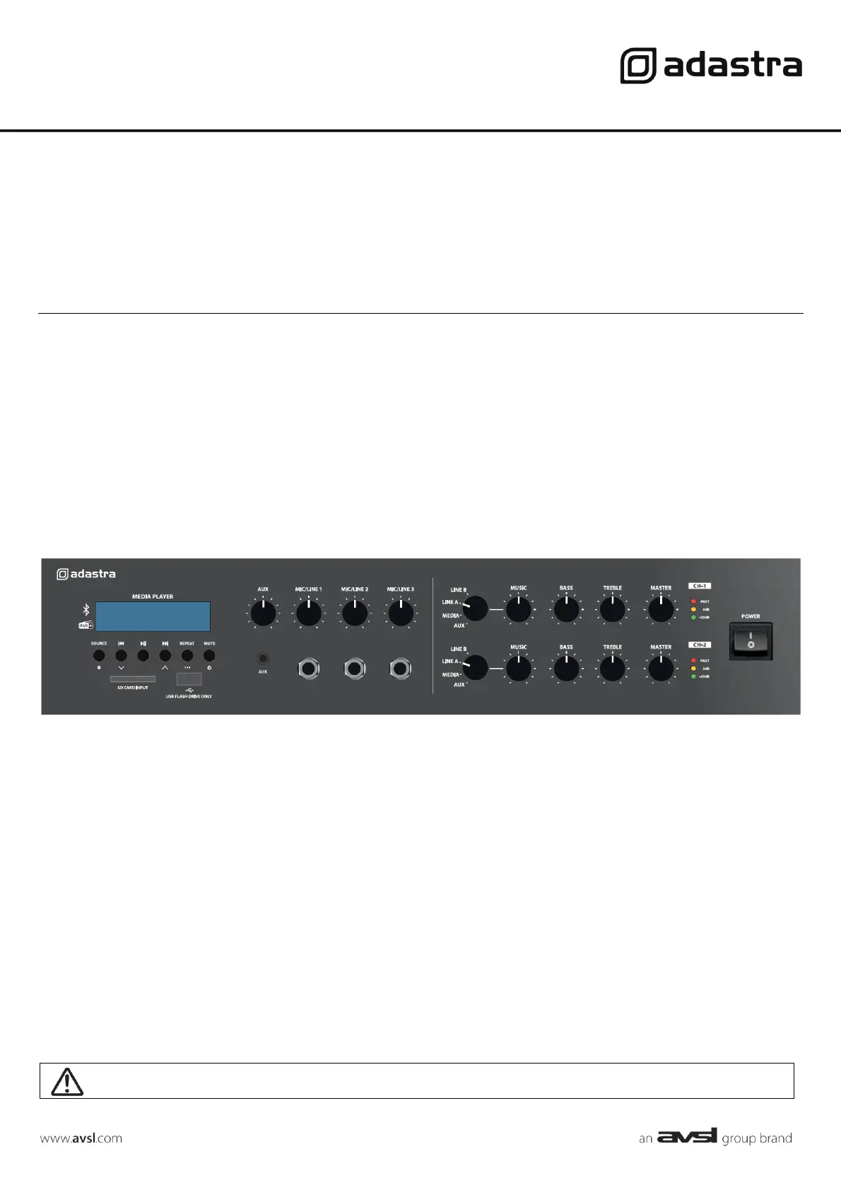
V-122 & V-242
DUAL ZONE 100V MIXER AMPLIFIERS WITH MEDIA PLAYER
Item ref: 953.251UK, 953.252UK
User Manual
Version 1.0
Caution: Please read this manual carefully before operating
Damage caused by misuse is not covered by the warranty
Product specificaties
| Merk: | Adastra |
| Categorie: | Receiver |
| Model: | V-122 |
Heb je hulp nodig?
Als je hulp nodig hebt met Adastra V-122 stel dan hieronder een vraag en andere gebruikers zullen je antwoorden
Handleiding Receiver Adastra

5 Maart 2024
7 Februari 2024
7 Februari 2024
30 Juni 2023
16 Juni 2023
3 Juni 2023
2 Juni 2023
2 Juni 2023
1 Juni 2023
31 Mei 2023
Handleiding Receiver
Nieuwste handleidingen voor Receiver
15 Juli 2026
15 Juli 2026
15 Juli 2026
15 Juli 2026
14 Juli 2026
14 Juli 2026
13 Juli 2026
13 Juli 2026
13 Juli 2026
13 Juli 2026