Xantech 789-44 Handleiding
Bekijk gratis de handleiding van Xantech 789-44 (3 pagina’s), behorend tot de categorie Splitter. Deze gids werd als nuttig beoordeeld door 42 mensen en kreeg gemiddeld 5.0 sterren uit 5 reviews. Heb je een vraag over Xantech 789-44 of wil je andere gebruikers van dit product iets vragen? Stel een vraag
Pagina 1/3
1
Modules & Connecting Blocks
INSTALLATION INSTRUCTIONS
12VDC
+12
VDC
GND
STATUS
IR IN
EMITTERS
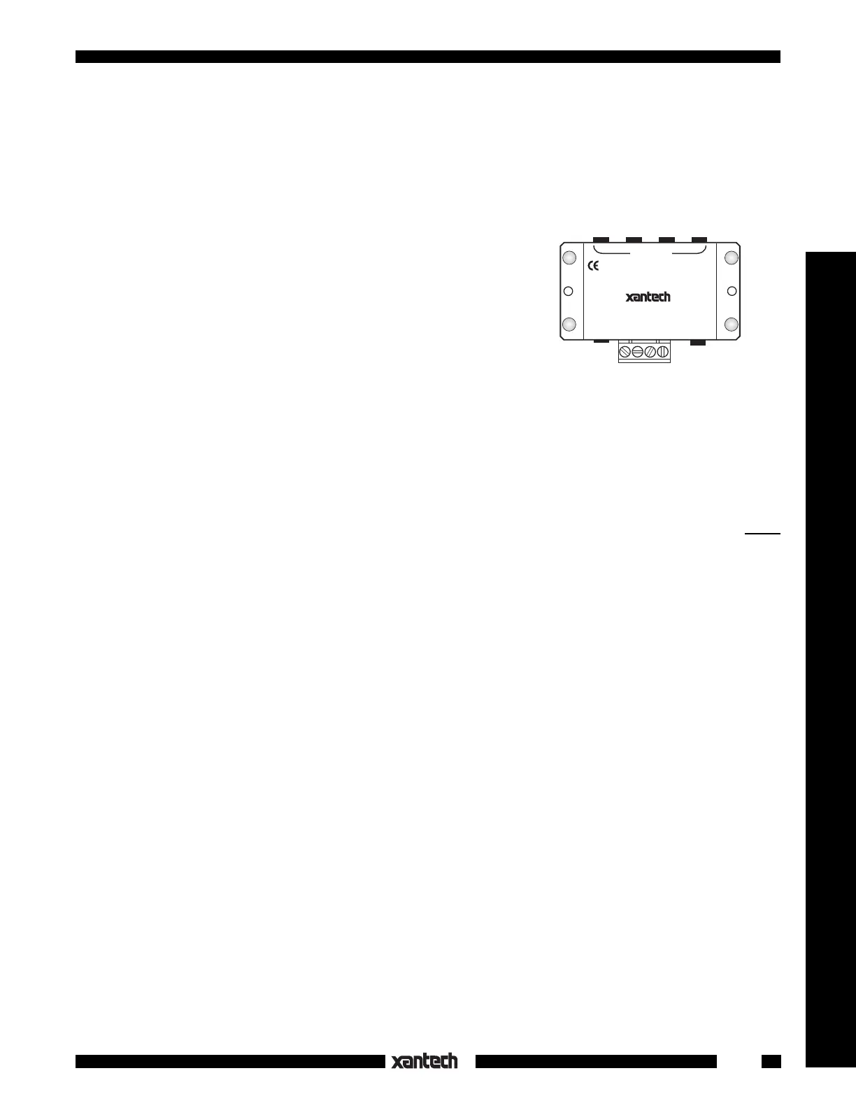
789-44
CONNECTING BLOCK
®
IR
RCVR
Fig. 1 Model 789-44 Connecting Block
The Model 789-44 provides a quick low cost means of connecting
Xantech IR receivers and keypads to four single or four dual
emitters, with a power supply, in an infrared repeater system. It
can also provide emitter expansion for various Xantech devices,
such as the 590, 710, 792-10, 795-20, 796-20, etc.. The STATUS
terminal provides a convenient tie point for voltage to drive the
STATUS indicator on certain Xantech products, such as the 780-
80 IR Receiver (refer to Fig. 3).
SPECIFICATIONS
•Inputs: 1 - Screw type 4-terminal plug-in. 1 - IR Receiver "IR RCVR" 3.5mm stereo mini jack. (See Caution
Note, Fig. 4)
•Outputs: 4 - Emitter ports (3.5mm mono mini jacks) parallel driven.
•Contains a 470 Ohm resistor in series with each emitter output.
•Xantech 282, 283, 284 & 286 Mini Emitters may be used.
•Power requirements: 12 volts DC. Uses 781RG or 782-00 Power Supplies. Note: A power supply
is not
connected to the 789-44 when it is used as an emitter expander.
•2.1 mm coaxial power jack.
•Dimensions: 2-15/16" W x 1-3/4" D x 13/16" H
INSTALLATION
Fig. 2, illustrates a typical installation using the 789-44 in an IR repeater system. A variety of Xantech IR
receivers and a keypad are shown. When configuring a system, please keep the following items in mind:
1.More IR receivers may be wired in parallel, in the same manner as shown, up to a maximum of twelve.
More than twelve is not recommended since IR noise picked up by the many IR receivers may cause
erratic operation and reduce remote control range.
Note: This restriction does not apply to Xantech SmartPad keypads. These may be added virtually
without limit, provided power supply requirements are taken into consideration. See item 3.
2.Be sure to connect the +12V, IR OUT and GND of each IR Receiver and keypad to the respective
+12VDC, IR IN and GND of the connecting block as shown.
3.Xantech SmartPads may be used by themselves or together with IR receivers as shown. When you
do this however, the higher current requirements of the keypads must be taken into consideration as
follows:
a)Each 730-00 keypad draws 65 mA. A SmartPad
2 or 3
draws 85ma.
b)Each IR receiver draws 10 to 20 mA (check specs. on actual model).
c)The max. current for proper operation from the 781RG Power Supply is 200 mA.
d)The max. current from the 782-00 Power Supply is 1000 mA.
e)When using combinations of keypads and receivers, do not exceed the max. current of the
power supplies as noted above.
789-44
CONNECTING BLOCK
Product specificaties
| Merk: | Xantech |
| Categorie: | Splitter |
| Model: | 789-44 |
Heb je hulp nodig?
Als je hulp nodig hebt met Xantech 789-44 stel dan hieronder een vraag en andere gebruikers zullen je antwoorden
Handleiding Splitter Xantech

5 Januari 2024
Handleiding Splitter
Nieuwste handleidingen voor Splitter
9 Januari 2026
8 Januari 2026
4 December 2025
29 November 2025
4 November 2025
2 November 2025
1 November 2025
6 Oktober 2025
29 September 2025
28 September 2025