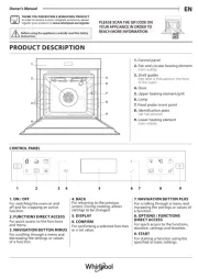
Whirlpool WGE555S0BB Handleiding
Bekijk gratis de handleiding van Whirlpool WGE555S0BB (24 pagina’s), behorend tot de categorie Oven. Deze gids werd als nuttig beoordeeld door 16 mensen en kreeg gemiddeld 4.4 sterren uit 8.5 reviews. Heb je een vraag over Whirlpool WGE555S0BB of wil je andere gebruikers van dit product iets vragen? Stel een vraag
Pagina 1/24

INSTALLATION INSTRUCTIONS
FREESTANDING ELECTRIC RANGE WITH DOUBLE OVENS
INSTRUCTIONS D'INSTALLATION POUR CUISINIÈRE
ÉLECTRIQUE AUTOPORTANTE AVEC FOURS DOUBLES
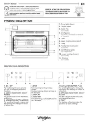
RANGE SAFETY
Table of Contents Table des matières
RANGE SAFETY .................................................................................... 1
INSTALLATION REQUIREMENTS....................................................... 2
Tools and Parts................................................................................... 2
Location Requirements ...................................................................... 2
Electrical Requirements - U.S.A. Only ............................................... 4
Electrical Requirements - Canada Only ............................................. 5
INSTALLATION INSTRUCTIONS......................................................... 5
Unpack Range.................................................................................... 5
Adjust Leveling Legs .......................................................................... 5
Install Anti-Tip Bracket ....................................................................... 6
Electrical Connection - U.S.A. Only ................................................... 7
Verify Anti-Tip Bracket Is Installed and Engaged............................. 12
Level Range ...................................................................................... 12
Complete Installation........................................................................ 13
Moving the Range ............................................................................ 13
SÉCURITÉ DE LA CUISINIÈRE ........................................................ 16
EXIGENCES D’INSTALLATION ........................................................ 17
Outils et pièces................................................................................ 17
Exigences d'emplacement.............................................................. 17
Spécifications électriques............................................................... 19
INSTRUCTIONS D'INSTALLATION.................................................. 19
Déballage de la cuisinière ............................................................... 19
Réglage des pieds de nivellement.................................................. 19
Installation de la bride antibasculement......................................... 20
Vérifier que la bride anti-basculement est bien
installée et engagée ........................................................................ 20
Réglage de l'aplomb de la cuisinière.............................................. 21
Achever l’installation ....................................................................... 22
Déplacement de la cuisinière.......................................................... 22
W10430958A
IMPORTANT:
Save for local electrical inspector's use.
IMPORTANT :
À conserver pour consultation par l'inspecteur local des installations électriques.
You can be killed or seriously injured if you don't immediately
You can be killed or seriously injured if you don't follow
All safety messages will tell you what the potential hazard is, tell you how to reduce the chance of injury, and tell you what can
happen if the instructions are not followed.
Your safety and the safety of others are very important.
We have provided many important safety messages in this manual and on your appliance. Always read and obey all safety
messages.
This is the safety alert symbol.
This symbol alerts you to potential hazards that can kill or hurt you and others.
All safety messages will follow the safety alert symbol and either the word “DANGER” or “WARNING.”
These words mean:
follow instructions.
instructions.
DANGER
WARNING

2
INSTALLATION REQUIREMENTS
Tools and Parts
Gather the required tools and parts before starting installation.
Read and follow the instructions provided with any tools listed
here.
Tools needed
Parts supplied
Check that all parts are included.
■ 3 - 10-32 hex nuts (attached to terminal block)
■ 3 - Terminal lugs
■ Oven racks
■ 2 - #12 x 1⁵⁄₈" screws (for mounting anti-tip bracket)
■ Anti-tip bracket (taped inside upper oven with package
containing literature)
Anti-tip bracket must be securely mounted to back wall or floor.
Thickness of floor may require longer screws to anchor bracket
to subfloor. Longer screws are available from your local
hardware store.
Parts needed
If using a power supply cord:
■ A UL listed power supply cord kit marked for use with ranges.
The cord should be rated at 250 volts minimum, 40 amps or
50 amps that is marked for use with nominal 1³⁄₈" (3.5 cm)
diameter connection opening and must end in ring terminals or
open-end spade terminals with upturned ends.
■ A UL listed strain relief.
Check local codes. Check existing electrical supply. See “Electrical
Requirements” section.
It is recommended that all electrical connections be made by a
licensed, qualified electrical installer.
Location Requirements
IMPORTANT: Observe all governing codes and ordinances.
■ It is the installer’s responsibility to comply with installation
clearances specified on the model/serial rating plate. The
model/serial rating plate is located behind the control panel.
■ To eliminate the risk of burns or fire by reaching over heated
surface units, cabinet storage space located above the surface
units should be avoided. If cabinet storage is to be provided,
the risk can be reduced by installing a range hood that projects
horizontally a minimum of 5" (12.7 cm) beyond the bottom of
the cabinets.
■ Cabinet opening dimensions that are shown must be used.
Given dimensions are minimum clearances.
■ The floor anti-tip bracket must be installed. To install the anti-tip
bracket shipped with the range, see “Install Anti-Tip Bracket”
section.
■ Grounded electrical supply is required. See “Electrical
Requirements” section.
IMPORTANT: To avoid damage to your cabinets, check with your
builder or cabinet supplier to make sure that the materials used will
not discolor, delaminate or sustain other damage. This range has
been designed in accordance with the requirements of UL and CSA
International and complies with the maximum allowable wood
cabinet temperatures of 194°F (90°C).
Mobile Home - Additional Installation Requirements
The installation of this range must conform to the Manufactured
Home Construction and Safety Standard, Title 24 CFR, Part 3280
(formerly the Federal Standard for Mobile Home Construction and
Safety, Title 24, HUD Part 280). When such standard is not
applicable, the Standard for Manufactured Home Installations,
ANSI A225.1/NFPA 501A or with local codes.
Mobile home installations require:
■ When this range is installed in a mobile home, it must be
secured to the floor during transit. Any method of securing the
range is adequate as long as it conforms to the standards listed
above.
■ Four-wire power supply cord or cable must be used in a mobile
home installation. The appliance wiring will need to be revised.
See “Electrical Connection” section.
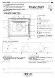
Tip Over Hazard
A child or adult can tip the range and be killed.
Install anti-tip bracket to floor or wall per installation instructions.
Slide range back so rear range foot is engaged in the slot of the anti-tip bracket.
Re-engage anti-tip bracket if range is moved.
Do not operate range without anti-tip bracket installed and engaged.
Failure to follow these instructions can result in death or serious burns to children and adults.
To verify the anti-tip bracket is installed and engaged:
• Slide range forward.
• Look for the anti-tip bracket securely attached to floor or wall.
• Slide range back so rear range foot is under anti-tip bracket.
• See installation instructions for details.
WARNING
Anti-Tip
Bracket
Range Foot
■ Tape measure
■ Level
■ Phillips screwdriver
■ Flat-blade screwdriver
■ Wrench or pliers
■ ³⁄₈" nut driver
■ Hand or electric drill
■ ¹⁄₈" (3.2 mm) drill bit

3
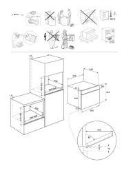
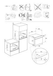
Product Dimensions
*Range can be raised approximately 1" (2.5 cm) by adjusting the
leveling legs.
**Model/serial/rating plates may be rotated up from behind the
control panel for viewing from the front of the range.
***Excludes handle. Dimension given is from wall to front of oven
door and will vary based on electric outlet receptacle installation.
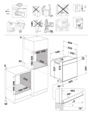
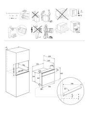
Cabinet Dimensions
Cabinet opening dimensions shown are for 25" (63.5 cm)
countertop depth, 24" (61.0 cm) base cabinet depth and
36" (91.4 cm) countertop height.
IMPORTANT: If installing a range hood or microwave hood
combination above the range, follow the range hood or microwave
hood combination installation instructions for dimensional
clearances above the cooktop surface.
A freestanding range may be installed next to combustible walls
with zero clearance.
Proper positioning of outlet shown above.
*Nothing located in shaded areas can extend more than
1½" (3.8 cm) from wall or range will not slide all the way back.
NOTE: 24" (61.0 cm) minimum when bottom of wood or metal
cabinet is covered by not less than ¹⁄₄" (0.64 cm) flame retardant
millboard covered with not less than No. 28 MSG sheet steel,
0.015" (0.4 mm) stainless steel, 0.024" (0.6 mm) aluminum or
0.020" (0.5 mm) copper.
30" (76.2 cm) minimum clearance between the top of the cooking
platform and the bottom of an unprotected wood or metal cabinet.
A.
35³⁄₄
" ±
¹⁄₈
" (90.8 cm ± 0.3 cm)
cooktop height (minimum)
with leveling legs screwed all
the way in*
B. Model/serial/rating plates
(located behind the control
panel)**
C.
47¹⁄₈
" ±
¹⁄₈
" (119.7 cm ±
0.3 cm) overall height
(minimum) with leveling legs
screwed all the way in*
D.
28¹⁄₂
" ±
¹⁄₄
" (72.4 cm ± 0.6 cm)
depth with handle
E. 26
¹⁄₈
" ±
¹⁄₈
" (66.4 cm ±
0.3 cm)***
F. 2 9
¹⁵⁄₁₆
" ±
¹⁄₁₆
" (76.0 cm ±
0.2 cm) width
A*
B**
C*
D
FE***
A. 18" (45.7 cm) upper cabinet
to countertop
B. 13" (33.0 cm) upper cabinet
depth
C. 30" (76.2 cm) min. opening
width.
D. For minimum clearance to the
top of the cooktop, see
NOTE.
E. 30" (76.2 cm) min. opening
width
F. Cabinet door or hinge should
not extend into cutout*
G. 1½" (3.8 cm) min. from right
side cabinet
H. 2" (5.1 cm) min. from floor
I. 7" (17.8 cm) min. from floor
J. 8" (20.3 cm) width
K. 3½"(8.91 cm) min. from floor
A
B
C
D
E
F
G
H
I
J
K
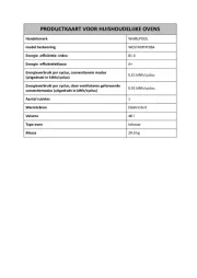
Product specificaties
| Merk: | Whirlpool |
| Categorie: | Oven |
| Model: | WGE555S0BB |
Heb je hulp nodig?
Als je hulp nodig hebt met Whirlpool WGE555S0BB stel dan hieronder een vraag en andere gebruikers zullen je antwoorden
Handleiding Oven Whirlpool
4 Augustus 2025
4 Augustus 2025
4 Augustus 2025
5 Juli 2025
4 Juli 2025
4 Juli 2025
4 Juli 2025
4 Juli 2025

4 Juli 2025
4 Juli 2025
Handleiding Oven
- Casselin
- XO
- Hitachi
- FriFri
- Maytag
- Waves
- Buschbeck
- Infiniton
- Tiger
- Bomann
- Blodgett
- Brother
- Brentwood
- Instant
- Taino
Nieuwste handleidingen voor Oven

9 Augustus 2025

9 Augustus 2025

8 Augustus 2025
8 Augustus 2025
8 Augustus 2025

8 Augustus 2025
7 Augustus 2025
6 Augustus 2025

6 Augustus 2025
6 Augustus 2025