Whirlpool W10791229 Handleiding
Bekijk gratis de handleiding van Whirlpool W10791229 (20 pagina’s), behorend tot de categorie Oven. Deze gids werd als nuttig beoordeeld door 35 mensen en kreeg gemiddeld 4.6 sterren uit 18 reviews. Heb je een vraag over Whirlpool W10791229 of wil je andere gebruikers van dit product iets vragen? Stel een vraag
Pagina 1/20

INSTALLATION INSTRUCTIONS
27" (68.6 CM) AND 30" (76.2 CM) ELECTRIC
SINGLE AND DOUBLE BUILT-IN OVEN
FLUSH INSTALLATION KIT
INSTRUCTIONS D’INSTALLATION
D'INSTALLATION ENSEMBLE D’INSTALLATION
EN AFFLEUREMENT POUR FOUR ÉLECTRIQUE
ENCASTRÉ SIMPLE ET DOUBLE
DE 27" (68,6 CM) ET 30" (76,2 CM)
W10826039C
BUILT-IN OVEN SAFETY 2 ..........................................................
INSTALLATION REQUIREMENTS 2 ..........................................
Tools and Parts 2 ....................................................................
Location Requirements 2 .......................................................
INSTALLATION INSTRUCTIONS 5 ...........................................
Prepare Built-In Oven 5 ..........................................................
Remove Oven Door(s) 5 ..........................................................
Replace Oven Door(s) 6 ..........................................................
Positioning Oven Feet 7 .........................................................
Replace Plastic Spacers 8 .....................................................
Install Oven 9 ..........................................................................
Install Deector Kit Bracket 9 .................................................
Complete Installation 10 .........................................................
SÉCURITÉ DU FOUR ENCASTRÉ 11 .......................................
EXIGENCES D’INSTALLATION 12 ...........................................
Outillage et pièces 12 .............................................................
Exigences d’emplacement 12 .................................................
INSTRUCTIONS D’INSTALLATION. 15 ....................................
Préparation du four encastré 15 .............................................
Dépose de la/des porte(s) du four 15 .....................................
Réinstallation de la/des porte(s) du four ............................ 16
Positionnement des pieds du four 17 .....................................
Remplacement des cales d’espacement en plastique 18 ......
Installation du four 19 ..............................................................
Installation du support de la trousse du déecteur 19 ............
Achever l’installation 20 ..........................................................
Table of Contents/Table des matières
IMPORTANT:
Save for local electrical inspector’s use.
IMPORTANT :
À conserver pour consultation par l'inspecteur local des installations électriques.
Flush Installation Kit Part Number
Ensemble d'installation en
affleurement référence
Size and Color
Dimensions et couleur
UL Listed for Model Numbers
Homologation UL pour les
modèles numéro
W10791232 27" (68.6 cm), black
27" (66,6 cm), noir
JJW2427DB, JJW2827DB
W10791228 27" (68.6 cm), stainless steel
27" (68,6 cm), acier inoxydable
JJW2427DS, JJW2827DS,
JJW2727DS
W10791233 30" (76.2 cm), black
30" (76,2 cm), noir
JJW2430DB, JJW2830DB
W10791229 30" (76.2 cm), stainless steel
30" (76,2 cm), acier inoxydable
JJW2430DS, JJW2430DP,
JJW2830DS, JJW2830DP,
JJW2730DS, JJW2430DS
W10837578 30" (76.2 cm), black
30" (76,2 cm), noir
JJW3430DB, JJW3830DB
W10837579 30" (76.2 cm), stainless steel
30" (76,2 cm), acier inoxydable
JJW3430DS, JJW3430DP,
JJW3830DS, JJW3830DP

2
BUILT-IN OVEN SAFETY
You can be killed or seriously injured if you don't immediately
You can be killed or seriously injured if you don't follow
All safety messages will tell you what the potential hazard is, tell you how to reduce the chance of injury, and tell you what can
happen if the instructions are not followed.
Your safety and the safety of others are very important.
We have provided many important safety messages in this manual and on your appliance. Always read and obey all safety
messages.
This is the safety alert symbol.
This symbol alerts you to potential hazards that can kill or hurt you and others.
All safety messages will follow the safety alert symbol and either the word “DANGER” or “WARNING.”
These words mean:
follow instructions.
instructions.
DANGER
WARNING
INSTALLATION REQUIREMENTS
Gather the required tools and parts before starting installation.
Read and follow the instructions provided.
IMPORTANT: Observe all governing codes and ordinances.
Refer to the following “Location Requirements” and the NOTE:
“Location Requirements” section of the Installation Instructions
provided with your built-in oven.
■ Cabinet opening dimensions that are shown must be used.
Given dimensions provide minimum clearance with oven.
■ Recessed installation area must provide complete
enclosure around the recessed portion of the oven.
■ Oven support surface must be solid, level, and ush with
bottom of cabinet cutout.
■ Floor must be able to support a single oven weight of
129 lbs (59 kg) for 27" (68.6 cm) models or 154 lbs (70 kg)
for 30" (76.2 cm) models.
■ Floor must be able to support a double oven weight of
251 lbs (114 kg) for 27" (68.6 cm) models or 288 lbs
(131 kg) for 30" (76.2 cm) models.
IMPORTANT: To avoid damage to your cabinets, check with
your builder or cabinet supplier to make sure that the materials
used will not discolor, delaminate, or sustain other damage. This
oven has been designed in accordance with the requirements
of UL and CSA International and complies with the maximum
allowable wood cabinet temperatures of 194°F (90°C).
Tools and Parts
Parts Supplied
■ Deector bracket
■ Plastic spacers - (4) single ovens, (6) double ovens
■ #8-18x
1
⁄ " screws - (2) for 27" (68.6 cm) models); (4) for 30" 4
(76.2 cm) models
Tools Needed
■ Phillips screwdriver
■ Measuring tape
■ Drill (for wall cabinet installations)
■
1
⁄ " (3 mm) drill bit (for wall cabinet installations)8
■ Level
■ Flat-blade screwdriver
Parts Supplied With Your Built-In Oven
■ #8-14 x 1" screws - (2) single ovens, (4) double ovens
included with built-in oven
■ (2) #8-18 x
3
⁄ " screws - bottom vent included with 8
built-in oven
■ (4) #8-18 x
3
⁄ " screws - included with built-in oven8
■ Bottom vent included with built-in oven
■ (2) Feet double oven included with built-in oven
■ (2) Front feet double oven included with built-in oven
Location Requirements

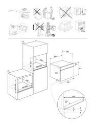
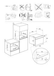
3
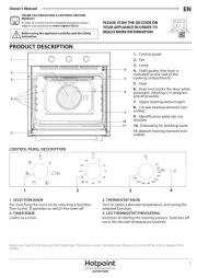
Front View
Deector Bracket Dimensions
27" (68.6 cm) Models
A.
³⁄4
" (19 mm) top cleat*
B. 27
¼
" (69.2 cm) minimum
width of ush inset cutout
C. 25
7
⁄8
" (65.7 cm) minimum
width of opening
D. 30
7
⁄16
" (77.3 cm) minimum
height of ush inset cutout
E. 29
11
⁄16
" (75.4 cm)
recommended cutout height
F.
11
⁄16
" (17 mm) side cleat*
G.
½
" x 2" (13 mm x 5.1cm)
spacer the entire depth
of the cutout*
H. Recommended junction
box location
I. 4
5
⁄8
" - 32" (11.7 - 81.3 cm)
bottom of cutout to oor
J. 25" (63.5 cm) minimum
depth of cutout
30" (76.2 cm) Models
A.
³⁄4
" (19 mm) top cleat*
B. 30
¼
" (76.8 cm) minimum
width of ush inset cutout
C. 28
7
⁄8
" (73.3 cm) minimum
width of opening
D. 30
7
⁄16
" (77.3 cm) minimum
height of ush inset cutout
E. 29
11
⁄16
" (75.4 cm)
recommended cutout height
F.
11
⁄16
" (17 mm) side cleat*
G.
½
" x 2" (13 mm x 5.1cm)
spacer the entire depth
of the cutout*
H. Recommended junction
box location
I. 4
5
⁄8
" - 32" (11.7 - 81.3 cm)
bottom of cutout to oor
J. 25" (63.5 cm) minimum
depth of cutout
Single Ovens Undercounter - Flush Installations
(without cooktop installed above)
Side View
*Cleats and spacers must be recessed 1
3
⁄ " (3.5 cm) from the 8
front of the cabinet.
27" (68.6 cm) Models
A. 26
15
⁄16
" (68.4 cm) overall width
30" (76.2 cm) Models
A. 29
15
⁄16
" (76.0 cm) overall width
Cabinet Dimensions - Single Ovens, Flush Installations
A 25" (63.5 cm) minimum cutout depth is required.
These dimensions will result in a ¼" (6 mm) reveal on the top,
a ¼" (6 mm) reveal on the sides, and a
1
⁄ " (3 mm) reveal on 8
the bottom of the wall oven.
The front face of the cleats and platform will be visible and
should be treated as a nished surface.
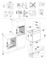
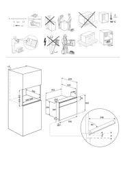
Single Ovens Installed in Cabinet - Flush Installation
27" (68.6 cm) Models
A. Recommended junction box
location
B.
³⁄4
" (19 mm) top cleat*
C. 27
¼
" (69.2 cm) minimum
width of ush inset cutout
D. 25
7
⁄8
" (65.7 cm) minimum
width of opening
E. 30
7
⁄16
" (77.3 cm) minimum
height of ush inset cutout
F. 29
11
⁄16
" (75.4 cm)
recommended cutout height
G.
11
⁄16
" (17 mm) side cleat*
H.
1
⁄2
" x 2" (13 mm x 5.1 cm)
spacer the entire depth
of the cabinet*
I. 4
1
⁄16
" (10.3 cm) bottom
of cutout to oor
30" (76.2 cm) Models
A. Recommended junction box
location
B.
³⁄4
" (19 mm) top cleat*
C. 30
¼
" (76.8 cm) minimum
width of ush inset cutout
D. 28
7
⁄8
" (73.3 cm) minimum
width of opening
E. 30
7
⁄16
" (77.3 cm) minimum
height of ush inset cutout
F. 29
11
⁄16
" (75.4 cm)
recommended cutout height
G.
11
⁄16
" (17 mm) side cleat*
H.
1
⁄2
" x 2" (13 mm x 5.1 cm)
spacer the entire depth
of the cabinet*
I. 4
1
⁄16
" (10.3 cm) bottom
of cutout to oor
Front View
*Cleats and spacers must be recessed 1
3
⁄ " (3.5 cm) from the 8
front of the cabinet.
Top View
27" (68.6 cm) Models
A.
1
⁄2
" x 2" (13 mm x 5.1 cm)
spacer the entire depth
of the cutout*
B. 25" (63.5 cm) depth
of cutout
C. 1
3
⁄8
" (3.5 cm) recess
from front of cabinet
D.
11
⁄16
" (17 mm) side cleat*
30" (76.2 cm) Models
A.
1
⁄2
" x 2" (13 mm x 5.1 cm)
spacer the entire depth
of the cutout*
B. 25" (63.5 cm) depth
of cutout
C. 1
3
⁄8
" (3.5 cm) recess
from front of cabinet
D.
11
⁄16
" (17 mm) side cleat*
*Cleats and spacers must be recessed 1
3
⁄ " (3.5 cm) from the 8
front of the cabinet.
A
A
BC
D
EFF
I
HHJ
G G
AA
B
C
D
E
F
G
G
I
HH
A A
B
D
D
C
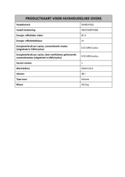
Product specificaties
| Merk: | Whirlpool |
| Categorie: | Oven |
| Model: | W10791229 |
Heb je hulp nodig?
Als je hulp nodig hebt met Whirlpool W10791229 stel dan hieronder een vraag en andere gebruikers zullen je antwoorden
Handleiding Oven Whirlpool
4 Augustus 2025
4 Augustus 2025
4 Augustus 2025
5 Juli 2025
4 Juli 2025
4 Juli 2025
4 Juli 2025
4 Juli 2025

4 Juli 2025
4 Juli 2025
Handleiding Oven
- ElectriQ
- Silver Style
- Hanseatic
- FORS
- Mestic
- BlueStar
- Emeril Lagasse
- Domo
- Jocel
- Haeger
- Zoppas
- Sauter
- Beem
- Hotpoint-Ariston
- Orbegozo
Nieuwste handleidingen voor Oven

9 Augustus 2025

9 Augustus 2025

8 Augustus 2025
8 Augustus 2025
8 Augustus 2025

8 Augustus 2025
7 Augustus 2025
6 Augustus 2025

6 Augustus 2025
6 Augustus 2025