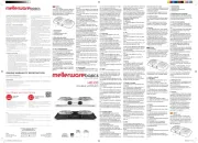
Whirlpool AKM 297 IX Handleiding
Bekijk gratis de handleiding van Whirlpool AKM 297 IX (8 pagina’s), behorend tot de categorie Fornuis. Deze gids werd als nuttig beoordeeld door 46 mensen en kreeg gemiddeld 4.7 sterren uit 23.5 reviews. Heb je een vraag over Whirlpool AKM 297 IX of wil je andere gebruikers van dit product iets vragen? Stel een vraag
Pagina 1/8

YOUR SAFETY AND THE SAFETY OF OTHERS ARE VERY IMPORTANT
This manual and the appliance itself provide important safety messages, to be read and observed at all times.
All Safety messages will tell you what the potential hazard is, tell you how to reduce the chance of injury, and tell you what
can happen if the instructions are not followed.
- The appliance must be disconnected from the power supply before carrying out any installation work.
- Installation and maintenance must be carried out by a qualified technician, in compliance with the manufacturer’s
instructions and local safety regulations. Do not repair or replace any part of the appliance unless specifically stated in
the user manual.
- Do not store or use gasoline or other flammable vapors and liquids in the vicinity of this appliance.
The electrical and gas connections must comply with local regulations.
- When the hob is installed, provide a multi-pole circuit breaker with a contact separation of at least 3 mm, that provides
full disconnection.
- Regulations require that the appliance is grounded.
- The power cable must be long enough for connecting the appliance, once fitted in its housing, to the power supply.
- Use only flexible or rigid metal hose for gas connection.
- If necessary, the electrical power cable must be replaced exclusively with a power cable having identical characteristics
to the original supplied by manufacturer (type H05V2V2-F 90°C or H05RR-F). This operation must be performed by a
qualified electrician.
- The manufacturer cannot be held responsible for any injury to persons or animals or damage to property arising from
failure to comply with these requirements.
- Do not use multiple plug adapters or extension cords.
- Do not pull the power supply cord in order to unplug the appliance.
- The electrical components must not be accessible to the user after installation.
- Do not touch the appliance with any wet part of the body and do not operate it when barefoot.
- This hob (class 3) is designed solely for private household use for cooking food. Do not use this appliance as a space
heater to heat or warm the room. Doing so may result in carbon monoxide poisoning and overheating of the hob.
The Manufacturer declines all responsibility for inappropriate use or incorrect setting of the controls.
- The appliance is not intended for use by persons (including children) with reduced physical, sensory or mental
capabilities, or with lack of experience and knowledge of the appliance, unless supervised or previously instructed in its
use by those responsible for their safety.
- Young children should be kept away from the appliance and supervised to ensure that they do not play with it.
- The use of a gas appliance produces heat and humidity in the room. Make sure the room is well-ventilated, or install an
extractor hood with exhaust duct.
- In case of prolonged use, additional ventilation may be necessary (by opening a window or increasing the hood
extraction speed).
- After use, make sure the knobs are in off position and close the main gas supply cock or the gas cylinder valve.
- Overheated oils and fats catch fire easily. Always remain vigilant when cooking foods rich in fat, oil or alcohol (e.g. rum,
cognac, wine).
- Keep the packaging materials out of the reach of children.
- Before cleaning or maintenance wait for hob to cool down.
- These instructions are valid only for those countries whose symbol is shown on the rating plate (under cooktop).
- This product is not intended to be installed and operated outdoors.
After unpacking the hob, make sure that it has not been damaged during transport. In the event of problems, contact the
dealer or your nearest After-sales Service.
TECHNICAL INFORMATION FOR THE INSTALLER
• Use protective gloves for handling, preparing and installing the product.
• This product can be embedded in a worktop 30 to 60 mm thick.
• If there is no oven beneath the hob, insert a separator panel that has a surface at least equal to the opening in the
work surface. This panel must be positioned at a maximum distance of 150 mm below the upper surface of the
work surface but, in no case less than 20 mm from the bottom of the hob.
• Before installation, make sure that:
- the local gas delivery conditions (nature and pressure) are compatible with the settings of the hob (see the
rating plate and injector table);
- the outer surfaces of the furniture or appliances adjacent to the hob are heat resistant according to local regulations;
- this appliance is not connected to a fume exhaust device. It shall be installed in accordance with current installation
regulations. Particular attention shall be given to the relevant requirements regarding ventilation;
- combustion products are discharged outdoors through specific hoods or wall and/or window mounted electrical fans.
GAS CONNECTION
IMPORTANT SAFETY INSTRUCTIONS
This is the safety alert symbol, pertaining to safety, which alerts users to potential hazards to themselves and others.
All safety messages will follow the safety alert symbol and either the terms:
DANGER Indicates a hazardous situation which, if not avoided, will cause serious injury.
WARNING Indicates a hazardous situation which, if not avoided, could cause serious injury.
WARNING If the information in this manual is not followed exactly, a fire or explosion may result
causing property damage or injury.
What to do if you smell gas:
- Do not try to light any appliance.
- Do not touch any electrical switch.
- Do not use any phone in your building.
- Immediately call your gas supplier from a neighbor’s phone. Follow the gas supplier’s instructions.
- If you cannot reach your gas supplier, call the fire department.
- Installation and service must be performed by a qualified installer, service agency or the gas supplier.
- Use appliance in well ventilated rooms only.
SAVE THESE INSTRUCTIONS
INSTALLATION
WARNING This operation must be performed by a qualified technician.
• The gas supply system must comply with local regulations.
• You can find specific local regulations for some countries in the paragraph
“Reference to Local Regulations”. If no information concerning your Country is
given, please ask details to your Installer.
• The connection of the hob to the gas pipe network or gas cylinder must be made by
means of a rigid copper or steel pipe with fittings complying with local regulations, or
by means of a continuous-surface stainless steel hose complying with local
regulations. The maximum length of the hose is 2 linear metres.
• Connect the elbow union to the main feed pipe of the hob and fit the seal
conforming with EN 549, as shown in the figure.
IMPORTANT: if a stainless steel hose is used, it must be installed so as not to touch
any mobile part of the furniture. It must pass through an area where there are no
obstructions and where it is possible to inspect it on all its length.
• After connection to the gas supply, check for leaks with soapy water. Light up the burners and turn the knobs from max
position to minimum position to check flame stability.
EN AKM 297 IX BUILT-IN FLUSH AND SEMI-FLUSH MOUNT HOB
5019 300 02708 Manufacturer: (VA) ITALY


ELECTRICAL CONNECTION
IMPORTANT: the data relevant to the voltage and power absorption are indicated on the rating plate.
ASSEMBLY
ADJUSTMENT TO DIFFERENT TYPES OF GAS
If the appliance is intended to operate with a different gas from the gas type stated on the rating plate and information label
on the top of the hob, change the injectors.
Remove the information label and keep it with the instructions booklet.
Use pressure regulators suitable for the gas pressure indicated in the Instruction.
• The gas nozzles must be changed by After Sales Service or a qualified technician.
• Nozzles not supplied with the appliance must be ordered from After Sales Service.
• Adjust the minimum setting of the taps.
NOTE: when liquid petroleum gas is used (G30/G31), the minimum gas setting screw must be tightened as far as it
will go.
IMPORTANT: should you experience difficulty in turning the burners knobs, please contact the After Sales Service
for the replacement of the burner tap if found to be faulty.
IMPORTANT: when gas cylinder is adopted, the gas cylinder or gas container must be properly settled (vertical
orientation).
REPLACING THE INJECTORS (see the injector table in the Instruction)
ADJUSTING MINIMUM GAS SETTING OF TAPS
REFERENCE TO LOCAL REGULATIONS
Connection to gas supply
Before connecting the appliance, make sure that the gas supply system complies with standards UNI-CIG 7129 and UNI CIG 7131.
Gas connection
The connection to the mains gas network or gas cylinder must be made using a rigid copper or steel pipe with fittings complying
with standards UNI-CIG 7129, or using a continuous-surface stainless steel hose complying with standards UNI-CIG 9891.
The maximum length of the hose is 2 m.
The pressure control valves to be used must comply with the UNI EN 12864 standard for gas cylinders and the UNI EN 88
standard for piped methane gas.
AFTER-SALES SERVICE
WARNING This operation must be performed by a qualified technician.
WARNING • The electrical connections must comply
with local regulations.
• The earthing of this appliance is
compulsory by law.
• Do not use an extension cord.
The appliance is designed for fitting a worktop as shown in the figure.
Note: Use the special adapters according to the thickness of the worktop.
Before inserting the hob, arrange the sealing strip around the entire perimeter of the recess.
For flush-mount models it is necessary to mill the recess perimeter area to a depth of 1.5 mm.
This milling must not be done for semi-flush mount models.
Installation is possible on various materials such as steel, marble, conglomerates, synthetic materials, wood and plastic
laminated wood, as long as they are resistant to a temperature of 90°C.
WARNING This operation must be performed by a qualified technician.
L
N
Earth
(yellow/green)
(*)
(*)
Sealing strip
(*) Hob mounting bracket without
adapter extensions for top
thicknesses of 60 to 70 mm.
Sealing strip
(*) Bracket with adapter
extensions:
- short for top thicknesses
of 50 to 70 mm.
- long for top thicknesses
of 30 to 50 mm.
• Remove grids (A).
• Extract burners (B).
• Use a 7 mm socket wrench to unscrew the injector to be
replaced (C).
• Replace it with the injector suitable for the new type of
gas.
• Re-assemble the injector in (D).
• With multiple crown burners, use a 7 mm open-end
spanner to replace the injector (E).
Before installing the hob, remember to affix the gas
calibration plate supplied with the injectors in such a way
that it covers the existing information relating to gas
calibration.
To ensure that the minimum setting is correctly adjusted, remove the knob and proceed
as follows:
• tighten screw to reduce the flame height (-);
• loosen screw to increase the flame height (+).
The adjustment must be performed with the tap in minimum gas setting position (small
flame) .
• The primary air of the burners does not need to be adjusted.
• At this stage, light up the burners and turn the knobs from max position to
minimum position to check flame stability.
Upon completion of adjustment, reseal using sealing wax or an equivalent material.
Before calling the After-Sales Service, make sure you can give the following information:
- type of fault or problem;
- exact model (written on the label affixed to the instruction/warranty);
- service number that follows the word SERVICE on the rating plate under the hob and
on the label affixed to instruction/warranty;
- your complete address and phone number.
If any repairs are required, please contact an authorised After-Sales Service, as indicated in the
warranty.
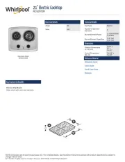
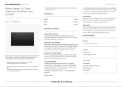
Product specificaties
| Merk: | Whirlpool |
| Categorie: | Fornuis |
| Model: | AKM 297 IX |
| Apparaatplaatsing: | Ingebouwd |
| Soort bediening: | Draaiknop |
| Kleur van het product: | Roestvrijstaal |
| Ingebouwd display: | Nee |
| Timer: | Nee |
| Gewicht: | 17900 g |
| Breedte: | 770 mm |
| Diepte: | 510 mm |
| Hoogte: | 75 mm |
| Snoerlengte: | 1.1 m |
| Soort materiaal (bovenkant): | Roestvrijstaal |
| Vermogen brander/kookzone 2: | 3000 W |
| Vermogen brander/kookzone 3: | 1750 W |
| Vermogen brander/kookzone 1: | 1000 W |
| Aantal branders/kookzones: | 5 zone(s) |
| Type kookplaat: | Gaskookplaat |
| Electronische ontsteking: | Ja |
| Type brander/kookzone 1: | Sudderen |
| Type brander/kookzone 2: | Groot |
| Type brander/kookzone 3: | Regulier |
| Aantal gaspitten: | 5 zone(s) |
| Aantal elektronische kook zones: | 0 zone(s) |
| Sudderbrander/kookzone diameter: | 50 mm |
| Reguliere brander/kookzone diameter: | 75 mm |
| Sudder brander/kookzone: | 1000 W |
| Normale brander/kookzone: | 1750 W |
| Controle positie: | Boven voorzijde |
| Aangesloten lading (elektrisch): | - W |
| Installatie compartiment breedte: | 771 mm |
| Installatie compartiment diepte: | 490 mm |
| Grote brander/kookzone diameter: | 100 mm |
| Grote brander/kookzone: | 3000 W |
| Stroom: | 0.3 A |
| Aangesloten lading (gas): | 60 W |
| Breedte kookplaat: | 77 cm |
| Hittesensor bescherming: | Ja |
| Materiaal pannensteun: | Gietijzer |
| Veiligheidsklep: | Ja |
| Restwarmte-indicator: | Nee |
| Installatiecompartiment breedte (min): | 750 mm |
| Extra grote hoge-snelheid kookzone: | 4000 W |
| Extra-grote brander/kookzone diameter: | 132 mm |
| Type brander/kookzone 4: | Regulier |
| Vermogen brander/kookzone 4: | 1750 W |
| Voedingsbron brander/kookzone 1: | Gas |
| Voedingsbron brander/kookzone 2: | Gas |
| Voedingsbron brander/kookzone 3: | Gas |
| Voedingsbron brander/kookzone 4: | Gas |
| Wokbrander: | Ja |
| Wokbrander positie: | Midden |
| Positie brander/kookzone 1: | Links voor |
| Positie brander/kookzone 2: | Links achter |
| Positie brander/kookzone 3: | Rechts achter |
| Positie brander/kookzone 4: | Rechts voor |
| Kookzone 1 vorm: | Rond |
| Kookzone 2 vorm: | Rond |
| Kookzone 3 vorm: | Rond |
| Kookzone 4 vorm: | Rond |
| AC-ingangsspanning: | 220 - 240 V |
| AC-ingangsfrequentie: | 50 - 60 Hz |
| Inbouw afzuigkap: | Nee |
| Voedingsbron brander/kookzone 5: | Gas |
| Type brander/kookzone 5: | Extra groot |
| Positie brander/kookzone 5: | Centraal |
| Vermogen brander/kookzone 5: | 4000 W |
| Kookzone 5 vorm: | Rond |
| Type elektrische ontsteking: | Ontsteking met één hand |
| Installatiecompartiment breedte (max.): | 771 mm |
Heb je hulp nodig?
Als je hulp nodig hebt met Whirlpool AKM 297 IX stel dan hieronder een vraag en andere gebruikers zullen je antwoorden
Handleiding Fornuis Whirlpool
15 Juli 2025

14 Juli 2025
14 Juli 2025

14 Juli 2025

4 Juli 2025
3 Juni 2025
13 Mei 2025

13 Mei 2025

13 Mei 2025

6 Mei 2025
Handleiding Fornuis
- Fisher Paykel
- Smeg
- Brixton
- Castor
- Dacor
- Qlima
- Cuisinart
- Delonghi
- Daewoo
- Schock
- Rangemaster
- Saro
- Adora
- Rinnai
- Xiaomi
Nieuwste handleidingen voor Fornuis
6 Augustus 2025
6 Augustus 2025
6 Augustus 2025
6 Augustus 2025
6 Augustus 2025
5 Augustus 2025

5 Augustus 2025

5 Augustus 2025
5 Augustus 2025

5 Augustus 2025