Watts BT-DRF-02 Handleiding
Watts Thermostaat BT-DRF-02
Bekijk gratis de handleiding van Watts BT-DRF-02 (2 pagina’s), behorend tot de categorie Thermostaat. Deze gids werd als nuttig beoordeeld door 141 mensen en kreeg gemiddeld 4.1 sterren uit 8 reviews. Heb je een vraag over Watts BT-DRF-02 of wil je andere gebruikers van dit product iets vragen? Stel een vraag
Pagina 1/2
PPLIMW15250Ba
BT-DRF-02
IMPORTANT!
Before starting work the installer should carefully read this Installation & Operation
Manual, and make sure all instructions contained therein are understood and observed.
- The thermostat should be mounted and maintained by specially trained personnel only.
People in the course of training are only allowed to handle the product under the
supervision of an experienced fitter. Subject to observation of the above terms, the
manufacture shall assume the liability for the equipment as provided by legal terms.
- All instructions in this Installation & Operation manual should be observed when
working with the controller. Any other application shall not comply with the regulations.
The manufacturer shall not be liable in case of incompetent use of the control. Any
modifications and amendments are not allowed for safety reasons.
The maintenance may be performed by service shops approved by the manufacturer
only.
- The controller functionality depends on the model and equipment. This installation
leaflet is part of the product and has to be obtained.
APPLICATION
- The thermostats range “BT-DRF-02” has been developed to control and manage all
type of Electrical heating system or materials.
- The controllers have been designed for use in residential rooms, office spaces and
industrial facilities.
Please find the Watts Vision system configuration documentation on:
http://www.wattselectronics.com
Table of content
1 Presentation
1.1 Keyboard
1.2 LED & Display
2 First Installation
2.1 Batteries installation
2.2 RF installation
2.2.1 With receivers
2.2.2 Case of central
2.3 Starting
3 Working mode definition
3.1 Manual mode Comfort
3.2 Manual mode Reduced
3.3 OFF mode
3.4 Anti-freeze mode
3.5 Timer mode
3.6 Reversible mode
3.7 AUTO mode
4 Special function
4.1 Keyboards lock Function
4.2 Open window function
4.3 Humidity measurement
4.4 Visualization
5 Parameter’s menu
6 Technical characteristics
7 Troubleshooting & Solution
8 Advanced installer’s parameters menu
1 Presentation
Electronic thermostat with LCD display specially designed to control different type of
heating systems.
It will be your best partner to optimize your energy consumption and increase your
comfort.
- Modern design with soft touch material
- Wireless Bidirectional communication 868 MHz
- Temporary override function
- Anti freeze function.
- EEPROM non volatile memory
- 2 AAA batteries
- 2 parameter menus (User and Installer)
- Humidity measurement (*)
In option
External sensor with several possibilities of regulation (Floor, combined…)
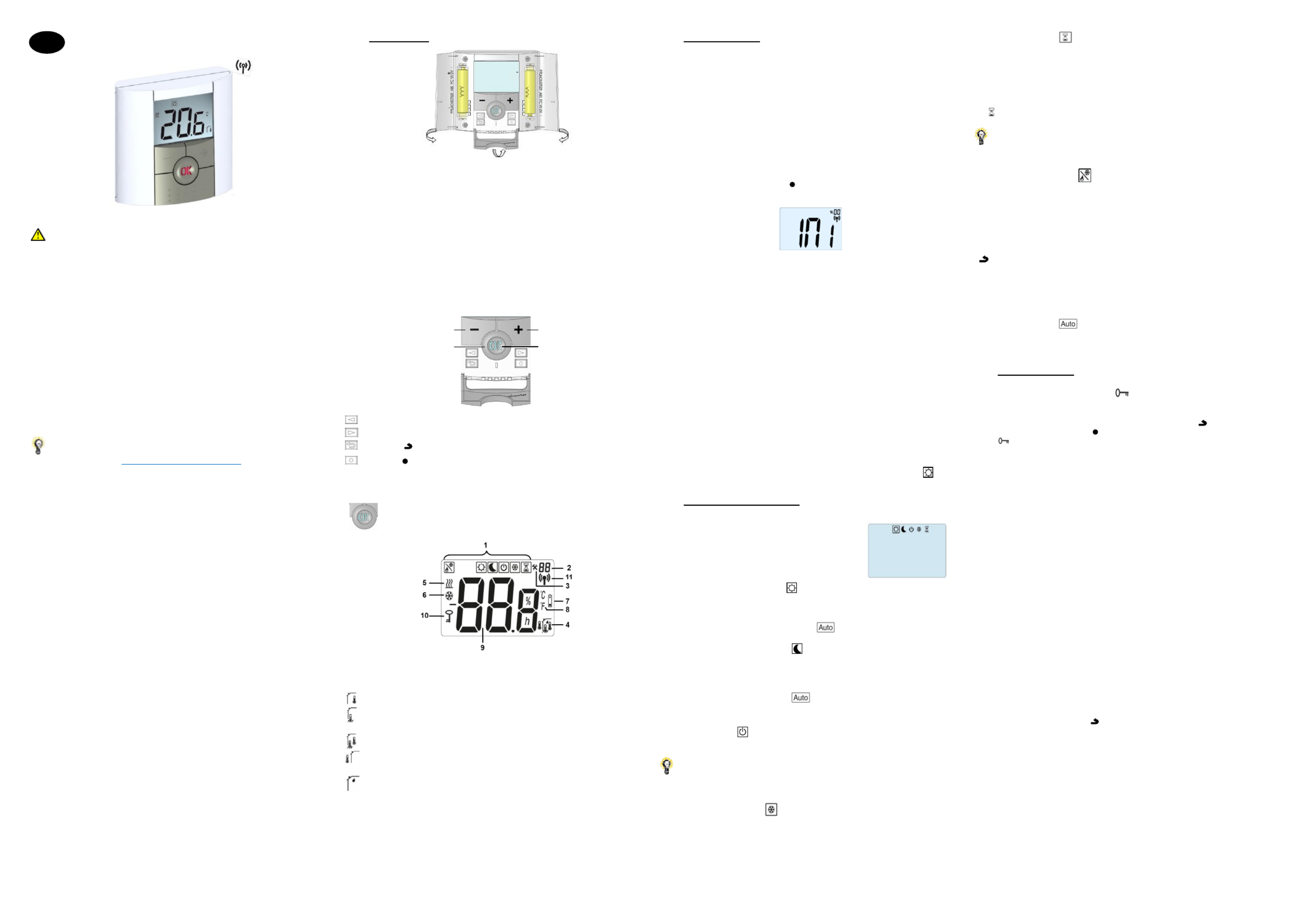
1.1 Keyboard
Left Navigation key (◄)
Right navigation key (►)
Escape key ()
Edition key ()
1.2 LED & Display
Color of “OK” LED when backlight is lit up:
Red Fix: heating demand (**)
Green Fix: cooling demand (**)
Green flash: validation is required
Red flash: error on sensor or batteries
1. Operating mode menu (active mode is framed).
2. Parameter number if “3” is displayed.
3. Installation Parameter menu.
4. Type of used sensor and displayed temperature
Regulation => Internal sensor.
Regulation => Floor sensor (Only available with receiver)
Regulation => Internal sensor with Floor limitation.
Regulation => outside temperature measured by external sensor (connected on the
back of thermostat)
Visualization of the humidity percentage (*)
5. Heating demand indication (**)
6. Cooling demand indication (**)
7. Low batteries indicator
8. °C or °F unit indicator
9. Setting or measured temperature if “4” is displayed.
Give the parameter name/value if “3” is displayed
10. Key lock indicator
11. RF indicator
2 First Installation
This section will guide you to set up your thermostat for the first time.
2.1 Batteries installation
- Open the two side’s covers and insert the 2 AAA Alkaline supplied batteries (or remove
the small protection sticker if the batteries are already installed in the compartment)
- Close the two side’s covers.
2.2 RF installation
Please have a look at the list of all receivers compatible with this thermostat in Technical
Caracteristics section.
2.2.1 With receivers
- First of all to configure your thermostat with the receiver, you must put your receiver in
RF initmode. (refer to the receiver leaflet, only the RF receivers of the same range are
compatibles)
- Press and maintain the edition key during 5s, then the parameter «» must be () INI
displayed.
The thermostat will send now the radio configuration signal to the receiver.
- After few seconds, the thermostat and the receiver should exit by their self the RF init
mode, this is the normal procedure to confirm a correct pairing.
- You can check the RF distance. Go to the room which must be regulated. Put your
thermostat on the final position (On the wall or table...), then put the thermostat in
Comfort mode (setting temperature position 37°C). Close the door and go to the receiver
to check if the new thermostat status has received.
- Return to the thermostat and switch it off. Check on the receiver again if it’s also
switched off.
If the RF signals were received correctly, adjust your setting temperature as you want.
If the RF signals weren’t received correctly, check the installation (Receiver position,
distance...) or restart the rules to be sure. RF init
Remark: To make the installation easier, it will be better to have the thermostat near to
the receiver during the configuration mode (a minimal distance of 1 meter must be
respected).
2.2.2 Case of central (BT-CT02)
The link is done with central (BT-CT02).
2.3 Starting
The thermostat is now ready to work. Default working mode is Comfort mode
3 Working mode definition
Your thermostat has several different working modes to allow you to adjust your unit
according to your life habitudes.
To change the working mode, open the small center
cover to access to the navigation keys or . Move (◄) (►)
the frame cursor on the desired working mode and press
(OK) to enter in the chosen operating mode.
3.1 Manual mode Comfort
Manual working mode, the comfort setting temperature will be followed all the time.
By pressing orkeys, the comfort setting temperature starts to blink and can be (-) (+)
adjusted.
Remark: Setpoint in Comfort mode is used in
mode
3.2 Manual mode Reduced
Manual working mode, the reduced setting temperature will be followed all the time.
By pressing orkeys, the reduced setting temperature starts to blink and can be (-) (+)
adjusted.
Remarks:
- Setpoint in Reduced mode is used in
mode
- In cooling mode, Reduced mode acts like the OFF mode (system is stopped)
3.3 OFF mode
Use this mode if you need to switch off your installation.
Be Careful: In this mode your installation can freeze.
At any time, when display is off, press on the key to display a few seconds the (Ok)
current temperature and time.
Remark: (◄)(►)To exit the operating mode, use the navigation keys or .
3.4 Anti-freeze mode
Use this mode if you want to protect your installation against freezing.
- The anti-freeze setting temperature is fixed and can be adjusted in the parameter
menu number , refer to chapter 5 (Default value 10°C). 06 ‘HG’
Remark: in cooling mode, Anti-freeze mode acts like the OFF mode (installation is
stopped).
3.5 Timer mode
The Timer mode allows you to adjust, the temperature for a special time. After this time,
thermostat will return to older current mode.
- You can first adjust, the desired setting temperature with or , press to (-) (+) (OK)
validate (Default value 24°C)
- In a second time, you can adjust the duration in hours “H” if below 24H, then in day “” d
with or , pressto start the function. (-) (+) (OK)
The logo will blink and the number of hours /days left is displayed until the end of the
period.
If you want to stop the Timer function before the end, set the duration period to “” no
with key or use the navigation keys or . (-) (◄)(►)
3.6 Reversible mode
The reversible mode allows you to choose the working mode for your installation.
By pressing on (-) or (+) keys, the selected working mode blinks and can be modified.
The user can choose:
- : the installation operates in heating mode (winter) Hot
- : the installation operates in cooling mode (summer). CLd
During this selection, the status LED will be red color if heating is selected or green color
if cooling is selected.
By pressing (OK) key, you validate you selection. By pressing (◄) or (►) key or the
() , keyyou come back to the current working mode of the thermostat.
Remarks:
- This menu is only available if the parameter “21” has been set to “REv” (refer to
chapter 8)
- This mode is not available if thermostat is linked with a central (BT-CT02)
3.7 AUTO mode
This mode appears when if a central is linked to your installation. In this case, the zone
of the thermostat follows the program created on the Central (BT-CT02).
4 Special function
4.1 Keyboards lock Function
Use this function to prevent all change of your settings (In a child room, public area…)
- To activate the Key lock function, first maintain the escape key pressed and press ()
simultaneously on the edition key . ( )
- The “” logo will be displayed on the screen.
Repeat the same procedure to unlock the key board.
4.2 Open window function
This function is able to stop heating if thermostat detects an unusual decrease of
temperature (open window).
Principle:
If the displayed temperature (internal or ambient sensor) decreases by 3°C or more
during a 5 minutes period (or less), the thermostat stops heating for 15 minutes. If the
temperature continues decreasing, it continues to stop.
During this stop, the room temperature will blink.
Return to normal mode:
The thermostat returns automatically to normal mode after the stop period.
The function can be overridden by pressing the button during the stop heating (OK)
phase.
The blinking temperature should stop to indicate the end of the detection.
Special cases:
- This function doesn't work if Thermostat is in Floor regulation
- This function doesn't work if Thermostat is in OFF / Antifreeze Mode
- If temperature is less than 10°C, thermostat will regulates at 10°C during the stop
phase (refer to chapter 5, parameter 06)
- This function doesn’t work in cooling configuration
4.3 Humidity measurement (*)
Thermostats measure the humidity in the air. This measure allows:
- To regulate the humidity in the air (refer to parameter chapter 8) 34
- To protect your system against condensation (refer to parameter chapter 8). 35
4.4 Visualization
With this function, you can quickly view the current temperatures of the different sensors
connected to your thermostat (floor, remote, external). On the main screen, press
several times on the escape key . This “scroll function” is only available on the main ( )
screen:
You will see in the order of each press:
1/ the setting temperature followed by the thermostat
2/ the ambient temperature
3/ if the external sensor is connected: the outside temperature
4/ the humidity percentage (*)
Remarks :
- refer to chapter 1.2 for icon meanings
- if Parameter “” is set on “” (refer to chapter 8), the remote sensor will be used as Sen Air
an external sensor.
Minus Key (-) Plus Key (+)
Validation Key (OK) Status LED
GB
Product specificaties
| Merk: | Watts |
| Categorie: | Thermostaat |
| Model: | BT-DRF-02 |
Heb je hulp nodig?
Als je hulp nodig hebt met Watts BT-DRF-02 stel dan hieronder een vraag en andere gebruikers zullen je antwoorden
Handleiding Thermostaat Watts

24 April 2024
24 April 2024
24 April 2024
24 April 2024
24 April 2024
24 April 2024
24 April 2024
24 April 2024
24 April 2024
24 April 2024
Handleiding Thermostaat
Nieuwste handleidingen voor Thermostaat
14 Juli 2026
12 Juli 2026
10 Juli 2026
9 Juli 2026
8 Juli 2026
12 Juni 2026
4 Juni 2026
3 Juni 2026
3 Juni 2026
3 Juni 2026