Velbus VMB1RYS Handleiding
Velbus Niet gecategoriseerd VMB1RYS
Bekijk gratis de handleiding van Velbus VMB1RYS (4 pagina’s), behorend tot de categorie Niet gecategoriseerd. Deze gids werd als nuttig beoordeeld door 189 mensen en kreeg gemiddeld 5.0 sterren uit 7 reviews. Heb je een vraag over Velbus VMB1RYS of wil je andere gebruikers van dit product iets vragen? Stel een vraag
Pagina 1/4
VMB1RYS
Velbus – Legen Heirweg 33, BE-9890 Gavere, Belgium – tel. +32 9 384 36 11 – e-mail: info@velbus.eu – www.velbus.eu PN-VMB1RYS-ed1
NEDERLANDS
Lees en begrijp deze handleiding en de veiligheidsinstructies vóór ingebruikname. Bewaar
deze handleiding voor verdere raadpleging.
BESCHRIJVING
Mini 1-kanaals wisselrelaismodule (voor standalone en Velbus werking).
GEBRUIK EN CONFIGURATIE
De VMB1RYS kan gebruikt worden als een standalone wisselrelais (met een externe
ingang voor het schakelen van het relais), of als onderdeel van een Velbus-systeem (1
relais, 4 virtuele relais, en 1 drukknopkanaal).
A. Standalone modus (standaardinstelling)
Standaard is de VMB1RYS ingesteld in standalone modus. In standalone modus stuurt
een knop die is aangesloten op de externe ingang het relais rechtstreeks aan. Selecteer
de bedrijfsmodus (toggle of drukknop) met de MODE/TERM-schakelaar aan de
achterkant (zie instructies op de modulesticker). In toggle-modus zal de externe ingang
het relais in een ON-OFF modus aansturen (telkens de ingang gesloten wordt, zal het
relais van open naar gesloten schakelen en vice versa). In drukknopmodus zal de
externe ingang het relais in een (ON)-OFF-modus aansturen (alleen als de ingang
gesloten is, is het relais ook gesloten, anders blijft het open).
STATUS LED:
•uit: NO open, NC gesloten
•aan: NO gesloten, NC open
•3 maal knipperen, pauze, 3 maal knipperen, enz: voedingsspanning te laag
PS LED: voedingsspanning gedetecteerd
Rx – Tx LEDS: niet van toepassing
B. Velbus-modus
Om de VMB1RYS te gebruiken als onderdeel van een Velbus systeem, sluit deze aan op
een Velbus-buskabel met minstens één andere Velbus-module en configureer deze met
de Velbus-configuratiesoftware VelbusLink. (Voor meer informatie over het Velbus-
systeem, raadpleeg www.velbus.eu.) Door het elektronische adres van de VMB1RYS te
wijzigen van FF(HEX)/255(DEC) naar een andere geldige waarde (01-253 DEC), wordt de
Velbus-modus geactiveerd. In Velbus-modus stuurt de externe ingang niet langer
rechtstreeks het relais aan, maar kunnen beide worden geconfigureerd met behulp van
de Velbus-configuratiesoftware VelbusLink. In Velbus-modus selecteert de
MODE/TEMP-schakelaar aan de achterkant de positie van de CAN-busafsluiter (open of
gesloten).
Om de VMB1RYS terug naar de standalone modus te schakelen, reset het elektronische
adres naar FF(HEX)/255(DEC) met behulp van de Velbus-configuratiesoftware
VelbusLink.
STATUS LED:
•uit: NO open, NC gesloten
•aan: NO gesloten, NC open
•traag knipperen: timer loopt
•2 maal knipperen, pauze, 2 maal knipperen, enz: communicatiefout
•3 maal knipperen, pauze, 3 maal knipperen, enz: voedingsspanning te laag
PS LED: voedingsspanning gedetecteerd
Rx LED: CAN bus pakket ontvangen
Tx LED: CAN bus pakket verstuurd
TECHNISCHE SPECIFICATIES
Max. belasting relais:
•resistief: 10 A @ 230 VAC / 10 A @ 30 VDC
•capacitief: 6 A @ 230 VAC
•inductief: 6 A @ 230 VAC
•spanningsbereik: 0-250 VAC, 0-30 VDC
Bedrijfsomstandigheden: -10 °C tot +55 °C
Voedingsspanning: 15 ± 3 VDC
Max. stroomverbruik: 50 mA
Afmetingen: 37 x 57 x 19 mm (L x B x D)
Beschermingsgraad: IP10
Aantal Velbus-kanalen: 6 (1 relais, 4 virtuele relais, 1 drukknopkanaal)
Voor een gedetailleerde lijst met technische specificaties, raadpleeg de productenpagina
op www.velbus.eu.
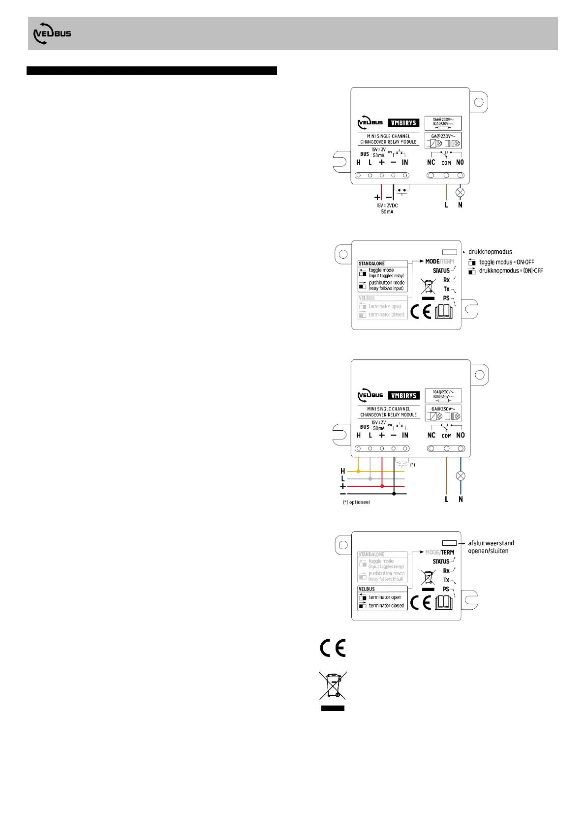
AANSLUITSCHEMA'S
A. Standalone modus (standaardinstelling)
B. Velbus-modus
Dit product voldoet aan alle geldende Europese richtlijnen en
voorschriften.
Dit symbool op het toestel of de verpakking geeft aan dat, als het na
zijn levenscyclus wordt weggeworpen, dit toestel schade kan
toebrengen aan het milieu. Gooi dit toestel (en eventuele batterijen)
niet bij het gewone huishoudelijke afval; het moet bij een
gespecialiseerd bedrijf terechtkomen voor recyclage. U moet dit
toestel naar uw verdeler of naar een lokaal recyclagepunt brengen.
Respecteer de plaatselijke milieuwetgeving.
Product specificaties
| Merk: | Velbus |
| Categorie: | Niet gecategoriseerd |
| Model: | VMB1RYS |
Heb je hulp nodig?
Als je hulp nodig hebt met Velbus VMB1RYS stel dan hieronder een vraag en andere gebruikers zullen je antwoorden
Handleiding Niet gecategoriseerd Velbus

1 December 2025
22 November 2024
22 November 2024
17 November 2024
24 Mei 2024
24 Mei 2024
22 Maart 2024
23 November 2023
8 Juli 2023
7 Juli 2023
Handleiding Niet gecategoriseerd
Nieuwste handleidingen voor Niet gecategoriseerd
27 Juli 2026
27 Juli 2026
27 Juli 2026
27 Juli 2026
25 Juli 2026
25 Juli 2026
25 Juli 2026
25 Juli 2026
24 Juli 2026
24 Juli 2026