Velbus VMB1BLS Handleiding
Velbus Niet gecategoriseerd VMB1BLS
Bekijk gratis de handleiding van Velbus VMB1BLS (4 pagina’s), behorend tot de categorie Niet gecategoriseerd. Deze gids werd als nuttig beoordeeld door 19 mensen en kreeg gemiddeld 4.1 sterren uit 3 reviews. Heb je een vraag over Velbus VMB1BLS of wil je andere gebruikers van dit product iets vragen? Stel een vraag
Pagina 1/4
VMB1BLS
Velbus – Legen Heirweg 33, BE-9890 Gavere, Belgium – tel. +32 9 384 36 11 – e-mail: info@velbus.eu – www.velbus.eu PN-VMB1BLS-ed1
NEDERLANDS
Lees en begrijp deze handleiding en de veiligheidsinstructies vóór ingebruikname.
Bewaar deze handleiding voor verdere raadpleging.
BESCHRIJVING
1-kanaals rolluikmodule (universele montage)
TECHNISCHE SPECIFICATIES
•relaiscontact
o230 VAC/ 16 A max.
o30 VDC / 12 A max.
•voeding: 12..18 VDC
•verbruik: max. 100 mA
•afmetingen: 72 x 59 x 24 mm
KENMERKEN
•bediening via VELBUS of met 2 drukknoppen
•programmeerbare timer
•terugmelding naar de bedieningsmodules
•led-indicaties voor
oomhoog- en omlaag werkingsmodi
ovoeding
ofoutmeldingen
•universele montage (bv. in rolluikkast)
•250 mogelijke adressen
BEDIENING
Tweeknops:
•kort drukken op ↑ of ↓: rolluik omhoog/omlaag tot einde of tot op tegengestelde
richting gedrukt wordt
•lang drukken op ↑ of ↓: rolluik omhoog/omlaag tot knop losgelaten wordt
Eenknops: zelfde principe als tweeknops. Na elke stilstand wordt de richting van de
motor omgedraaid. Andere acties voor gebruik in een Velbus systeem kunnen
geprogrammeerd worden via de Velbuslink* software.
Voor algemene informatie over de installatie en configuratie van Velbus,
raadpleeg de Installatiehandleiding en andere documentatie op www.velbus.eu.
LED-INDICATIES
•LED PS (voeding) ⑫:
ocontinu aan: voeding OK
oOFF: voeding niet OK
•LED up ⑬: knippert terwijl rolluik omhoog gaat
•LED down ⑭: knippert terwijl rolluik omlaag gaat
•In geval van een fout, zullen de LED up ⑬ en LED down⑭ simultaan knipperen
als volgt:
o2 x knipperen, pauze, 2 x knipperen, enz.: communicatiefout (enkel indien
aangesloten op Velbus data bus en adres ≠ FF)
o3 x knipperen, pauze, 3 x knipperen, enz.: voedingsspanning te laag
o4 x knipperen, pauze, 4 x knipperen, enz.: voedingsspanning te hoog
OPMERKINGEN
1. ADRESSERING IN EEN VELBUS INSTALLATIE
Wij raden aan de VMB1BLS modules vooraf te adresseren. Sluit hiervoor de VMB1BLS
aan op een Velbus (test) installatie en gebruik de functie “Adresbeheer” met
automatische detectie in Velbuslink* (voor uitgebreide instructies, zie de VMB1BLS
gebruikershandleiding op www.velbus.eu > Downloads). Velbuslink zal de VMB1BLS
automatisch detecteren bij bediening van de drukknop “omlaag” of “omhoog”
(verbind aansluiting ④ of ⑥ met ⑤).
Indien de VMB1BLS niet vooraf geadresseerd werd, kan dit achteraf gebeuren als
volgt:
•in Velbuslink, klik rechts op het rolluikkanaal van een VMB1BLS die geadresseerd
moet worden en selecteer “Bedienen”
•verifieer welk geïnstalleerd rolluik omhoog of omlaag gaat
•u weet nu welke VMB1BLS module in Velbuslink met dit rolluik overeenkomt
2. STANDALONE GEBRUIK
De VMB1BLS kan ook gebruikt worden als standalone rolluikbesturing (zonder Velbus
installatie). In dat geval moet de VMB1BLS gewoon gevoed worden met 12..18 V DC /
100 mA (aansluitingen ⑦ en ⑧) zonder de BUS H ⑨of BUS L⑩ aan te sluiten. De
bediening van het rolluik kan in dat geval rechtstreeks gebeuren via één of twee
drukknoppen aangesloten op “knop omhoog” ④, “knop common” ⑤ en “knop
omlaag” ⑥.
3. AFSLUITER
Elke Velbus module beschikt over een afsluiter (terminator switch of jumper) ⑪. In
een modale Velbus installatie moeten alle afsluiters open zijn behalve twee. De
gesloten afsluiters bevinden zich best zo ver mogelijk van elkaar.
In een standalone installatie van de VMB1BLS is de toestand van de afsluiter van geen
belang.
*Versie 9.28 of hoger
Dit product voldoet aan alle geldende Europese richtlijnen en
voorschriften.
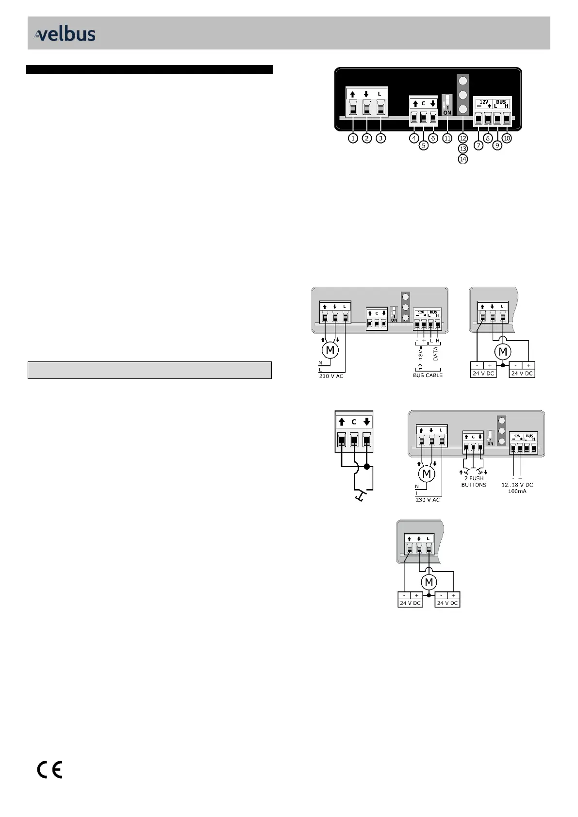
AANSLUITSCHEMA'S
Aansluitingen
motor omhoog
⑥
drukknop common
motor omlaag
⑦
bus voeding -
lijnaansluiting
⑧
bus voeding + (12..18 V DC)
④
drukknop omhoog
⑨
bus data L
⑤
drukknop omlaag
⑩
bus data H
Overige elementen
⑪
afsluiter
⑬
LED up
⑫
LED PS (voeding)
⑭
LED down
1. VELBUS
230 V AC MOTOR
24 V DC MOTOR
2. STANDALONE
1 DRUKKNOP
230 V AC MOTOR
24 V DC MOTOR
Product specificaties
| Merk: | Velbus |
| Categorie: | Niet gecategoriseerd |
| Model: | VMB1BLS |
Heb je hulp nodig?
Als je hulp nodig hebt met Velbus VMB1BLS stel dan hieronder een vraag en andere gebruikers zullen je antwoorden
Handleiding Niet gecategoriseerd Velbus

1 December 2025
22 November 2024
22 November 2024
17 November 2024
24 Mei 2024
24 Mei 2024
22 Maart 2024
23 November 2023
8 Juli 2023
7 Juli 2023
Handleiding Niet gecategoriseerd
Nieuwste handleidingen voor Niet gecategoriseerd
8 Juni 2026
8 Juni 2026
8 Juni 2026
8 Juni 2026
8 Juni 2026
8 Juni 2026
8 Juni 2026
8 Juni 2026
8 Juni 2026
8 Juni 2026