Valcom VIP-176A-IC Handleiding
Valcom Niet gecategoriseerd VIP-176A-IC
Bekijk gratis de handleiding van Valcom VIP-176A-IC (4 pagina’s), behorend tot de categorie Niet gecategoriseerd. Deze gids werd als nuttig beoordeeld door 6 mensen en kreeg gemiddeld 4.6 sterren uit 2 reviews. Heb je een vraag over Valcom VIP-176A-IC of wil je andere gebruikers van dit product iets vragen? Stel een vraag
Pagina 1/4
1 947572
CAUTION: To reduce the risk of electric shock,
Do not remove cover.
No user serviceable parts inside.
Refer servicing to qualified service personnel.
CAUTION
RISK OF ELECTRIC SHOCK
DO NOT OPEN
This symbol indicates that dangerous
voltage constituting a risk of electric
shock is present within this unit.
This symbol indicates that there are
important operating and maintenance
instructions in the literature accompanying
this unit.
ISSUE 1
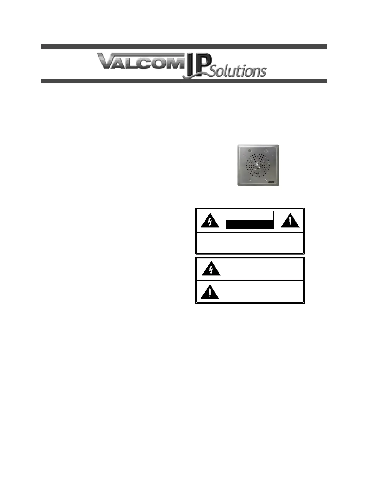
VIP-176A-IC
InformaCast
®
Compliant
SIP Door Intercom
INTRODUCTION
The VIP-176A-IC InformaCast Compliant SIP
Talkback Door Intercom allows communication to
SIP-based telephone systems or Valcom
Enhanced Station Port adapters via an IP-based
network.
SPECIFICATIONS
Access Methods
InformaCast Server
SIP – enabled telephone system
PBX, FXO Port w/Valcom Enhanced Station
Port
POTS telephone set w/Valcom Enhanced
Station Port
Valcom M Cast Page Group
Features
RJ-45 for network connection
1 Form C Smart Relay (optional)
Network activity LEDs
Power over Ethernet (PoE) 802.3af
compatible
Dimensions/Weight:
4.88” H x 4.88" W x 2.5" D (including button)
(12.4cm H x 12.4cm W x 6.4cm D)
Weight: 0.82 lbs. (0.37 kg)
Nominal Power Requirements
Via 802.3af PoE Ethernet Switch: Class 3
Environment
Network Interface:
Temperature: 0 to +40° C
Humidity: 0 to 85% non-precipitating
Suitable for indoor or outdoor installation,
protected from direct precipitation.
Precautionary Designations
FCC Information
This equipment has been tested and found to
comply with the limits for a Class A digital
device, pursuant to Part 15 of the FCC Rules.
These limits are designed to provide
reasonable protection against harmful
interference when the equipment is operated
in a commercial environment. This
equipment generates uses and can radiate
radio frequency energy and if not installed
and used in accordance with the instruction
manual, may cause harmful interference to
radio communications. Operation of this
equipment in a residential area may cause
harmful interference in which case the user
will be required to correct the interference at
his own expense.
Product specificaties
| Merk: | Valcom |
| Categorie: | Niet gecategoriseerd |
| Model: | VIP-176A-IC |
Heb je hulp nodig?
Als je hulp nodig hebt met Valcom VIP-176A-IC stel dan hieronder een vraag en andere gebruikers zullen je antwoorden
Handleiding Niet gecategoriseerd Valcom

30 Mei 2026
27 Mei 2026
27 Mei 2026
26 Mei 2026
26 Mei 2026
26 Mei 2026
25 Mei 2026
8 April 2026
7 April 2026
6 April 2026
Handleiding Niet gecategoriseerd
Nieuwste handleidingen voor Niet gecategoriseerd
8 Juni 2026
8 Juni 2026
8 Juni 2026
7 Juni 2026
7 Juni 2026
7 Juni 2026
7 Juni 2026
7 Juni 2026
6 Juni 2026
6 Juni 2026