Uni-T UT372 Handleiding
Uni-T Kilometerteller UT372
Bekijk gratis de handleiding van Uni-T UT372 (71 pagina’s), behorend tot de categorie Kilometerteller. Deze gids werd als nuttig beoordeeld door 128 mensen en kreeg gemiddeld 4.8 sterren uit 6 reviews. Heb je een vraag over Uni-T UT372 of wil je andere gebruikers van dit product iets vragen? Stel een vraag
Pagina 1/71
button to set to 0 or 1. 0 represents disabling LED laser and 1 for
enabling the laser.
Model UT371/UT372 is a stable, safe and reliable digital non- contact Tachometer.
This Tachometer can measure RPM and counts. RPM range is 10 ~ 99999
while counts range is 0 ~ 99999.
Open the package case and take out the Meter. Check the following items
carefully for any missing or damaged part:
Description
English Operating Manual
Reflecting Tape
USB Interface Cable (UT372 only)
Software(UT372 only)
1.5V Battery (LR6)
Overview
This Operating Manual covers safety information related to the Tachometer.
Please read the relevant information carefully and observe all the Warnings
and Notes strictly.
Item
1
2
3
4
5
Qty
1 piece
10 pieces
1piece
1 piece
4 pieces
Unpacking Inspection
In the event you find any missing or damaged item, please contact your dealer
immediately.
This Meter complies with IEC61010-031 and IEC61326 standards as well as
Pollution Degree 2 requirement
Use the Meter only as specified in this operating manual, otherwise the
protection provided by the Meter may be impaired.
In this manual, a Warning identifies conditions and actions that pose hazards to
the user, or may damage the Meter or the equipment under test.
A Note identifies the information that user should pay attention to.
Safety Information
Do not point laser directly at eye.
Replace the battery as soon as the battery indicator
appears.
When the battery is between 4.5V ~4.8V, the battery indicator appears.
When the battery is between 4.3V ~ 4.5V, battery indicator blinking,
the Meter will be turned off after 1 minute.
When opening the battery door, make sure the Meter is powered off.
When servicing the Meter, use only the replacement parts with the
same model or identical electrical specifications.
The internal circuit of the Meter shall not be altered at will to avoid
damage of the Meter and any accident.
Warning
Before using the Meter inspect the case. Do not use the Meter if it is
damaged or the case (or part of the case) is removed. Look for cracks or
missing plastic.
Soft cloth and mild detergent should be used to clean the surface
of the Meter when servicing. No abrasive and solvent should be
used to prevent the surface of the Meter from corrosion, damage
and accident.
Turn the Meter off when it is not in use and take out the battery
when not using for a long time.
Constantly check the battery as it may leak when it has been using
for some time, replace the battery as soon as leaking appears.
A leaking battery will damage the Meter.
International Electrical Symbols
Warning. Refer to the Operating Manual
Low Battery Indication
Conforms to Standards of European Union
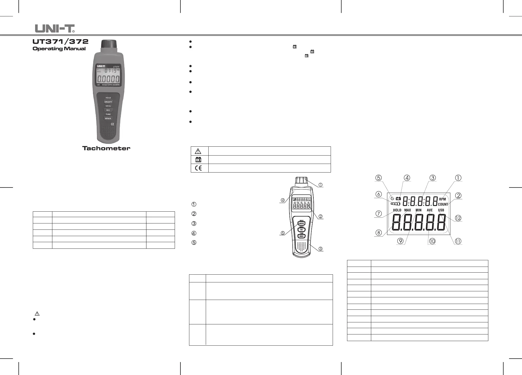
Figure 1
The Meter Structure
(See Figure 1)
Tachometer Light Source.
LCD Display.
USB Port (UT372 only)
Housing
Functional Buttons
Functional Buttons
The table below offers information about the functional button operations.
Button Operation Performed
Press once to turn the meter on.
Press and hold for 1 second to turn it off.
When measuring RPM and Counts, press once to enter the Hold mode. Press it
again to exit hold mode.
When measuring RPM and Counts, press it to toggle between RPM and Counts
feature.
Press and hold for 1 minute to enter setup feature, the LCD displays USB. After that,
each pressing steps through LED / SR / AOFF / CLK / settings, then exits the setup
and accesses RPM or Count, You could press ON/OFF button to exit setup mode
and return to normal measurement mode at any time.
Press this button to choose Max./Min./Average/Zeroing/Setting options.
Under Tach measurement mode, press M/M/A button to select MAX/MIN/AVE and
normal measurements.
After entering USB/LED/SR/AOFF/CLK mode, press this button to set to 0/ 1 and
adjust the time.
ON/OFF
R/C
M/M/A
Do not use or store the Meter in an environment of high temperature,
humidity, explosive, inflammable and strong magnetic field. The
performance of the Meter may deteriorate after dampened.
Setup
A. USB
PressR/Cbutton to select USB feature after turning on the Meter. Then press
M/M/A
button to set to 0 or 1. 0 represents disabling USB and 1 for enabling USB.
B. LED
PressR/C button to select LED feature after turning on the Meter. Then press
M/M/A
C. SR (Sampling Rate)
PressR/C button to select SR feature after turning on the Meter. Then press
M/M/A
button to adjust within 005 ~ 255. Press and hold M/M/A button to
D. AOFF
PressR/C button to select AOFF feature after turning on the Meter. Then
M/M/A press button to set to 0 or 1. 0 represents disabling auto power off and
1 for enabling the function.
With the function enabled, the meter will automatically power off if buttons are
inactive for 10minutes. Press ON/OFF again to wake up the meter.
E. CLK
Press R/Cbutton to select CLK feature after turning on the Meter. Then press
M/M/A
button to set to 0 or 1. 0 is for h:m time format and 1 for m:s format.
Display Symbols (see figure 2)
Figure 2
1
2
3
4
5
6
7
8
9
10
11
12
Unit of Tachometer
Unit of Counts
Time
The battery is low.
Indicator of Sleep Mode
Measurement of RPM and Counts
Data Hold is on
Display of Maximum reading
Display of Minimum reading
Display of Average reading
USB is on
Display of Measurement reading
Number Meaning
access quick setting.
Product specificaties
| Merk: | Uni-T |
| Categorie: | Kilometerteller |
| Model: | UT372 |
Heb je hulp nodig?
Als je hulp nodig hebt met Uni-T UT372 stel dan hieronder een vraag en andere gebruikers zullen je antwoorden
Handleiding Kilometerteller Uni-T

6 Maart 2024
6 Maart 2024
6 Maart 2024
18 Mei 2023
Handleiding Kilometerteller
Nieuwste handleidingen voor Kilometerteller
16 December 2024
17 November 2024
17 November 2024
5 Maart 2024
27 November 2023
13 September 2023
13 September 2023
13 September 2023
5 Juli 2023
2 Juli 2023