Supermicro SuperServer SYS-522B-WR Handleiding
Supermicro Server SuperServer SYS-522B-WR
Bekijk gratis de handleiding van Supermicro SuperServer SYS-522B-WR (1 pagina’s), behorend tot de categorie Server. Deze gids werd als nuttig beoordeeld door 14 mensen en kreeg gemiddeld 4.3 sterren uit 3 reviews. Heb je een vraag over Supermicro SuperServer SYS-522B-WR of wil je andere gebruikers van dit product iets vragen? Stel een vraag
Pagina 1/1
ItemtnDescripio
1t P S sRedundanowerupplyModule
2S Pterialor
3t B LAN PtDedicaedMCor
4Twoenor U 3.2 GSB 1 Pts(blue)
5Two45or RJ 1GbE LAN Pts
6A PtVGor
Imt tnteSloDescripio
PCIe 5.0 x St (FH, . L)16lo123”
PCIe 5.0 x St (FH, . L)16lo123”
PCIe 5.0 x8 St P)lo(L
PCIe 5.0 x8 St P)lo(L
+
JNVME2
DESIGNED IN USA
SAN MAC
MAC CODE
REV:1.01
X14SBW-TF
IPMI CODE
BIOS LICENSE
BAR CODE
JSXB1A
JUIDB1
LED6
LAN1LAN2
LEDBMC
JNCSI
BMC_LAN
USB0/1 (3.0)
COM1
MH2
JPL3
JPL2
JPL1
JMP1
JMP2
COM2
LED4
JM2_1JM2_2
LED7
MH13
MH12
MH10
MH11
JDB2
JPRG1
JPFR3
JPFR2
JDB3
JPT1
JBT1
BT1
JSXB2: PCIe 5.0 p1-x8 (in x16)
JSXB1B: PCIe 5.0 p1-x16 + x16
USB2/3
JF1
LEDPWR
JNVME4
JTMED
MH1
VGA
JTPM1
JVRM1
JVRM2
JSYSID2
JSYSID1
JNVME1
MH8
JPI2C1
JRK1
JSTBY1
JDB1
JPWR3
JPWR1JPWR2
MH7
FAN1FAN2
FAN3
MH5
FAN4
FAN5
FAN6
JL1
JNVME3
JIPMB1
MH9
JBPNI2C1JSEN1
JNVI2C1
SATA0–7
JSXB1C
MH6
MH15
DIMME1
DIMMF1
DIMMG1
DIMMH1
DIMMD1
DIMMC1
DIMMB1
DIMMA1
http://www.supermicro.comMNL-2689-QRGRev. 1.0
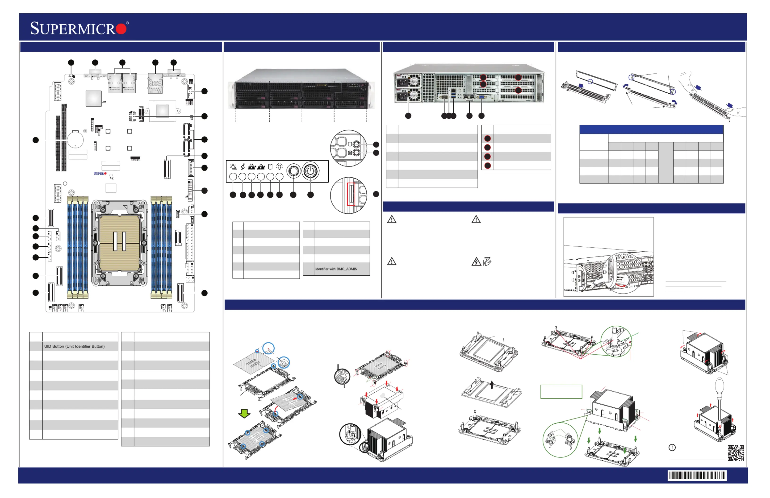
SuperServer 522B-WR Quick Reference Guide
Caution
Board Layout
Rear View and Features
Front View and Features
BMC Password Label
Memory
CPU Installation, supporting a single Intel® Xeon® 6 Processor (LGA 4710)
12
6
7
5
8
3
For mofore inrmation go to:
ht:tp//www.upo.sermcricom/srtuppo
PRODUCT RESOURCES:
B. Assembling the Processor Heatsink Module (PHM)
1. If this is a new heatsink, the thermal grease has been preapplied. Otherwise, apply the proper
amount of thermal grease.
2. Hold the processor carrier assembly so the processor's gold contacts are facing up, then align
the holes of the processor carrier assembly with the holes on the heatsink. Press the processor
carrier assembly down until it snaps into place. The plastic clips of the processor carrier assembly
will lock at the four corners.
3. Examine all corners to ensure that the plastic clips on the processor carrier assembly are firmly
attached to the heatsink.
Pin 1
a
c
b
d
A. Creating the Intel Xeon 6 CPU Carrier Assembly
1. Locate small gold triangle (Pin 1) on processor and corresponding
hollowed triangle on carrier.
2. Using the triangles as a guide, carefully align and place Point A of
the processor into the carrier. Gently snap into place to fasten onto
Point B.
Pin 1
Make sure the lever
is pressed down before
installing the processor.
A
B
Processor Carrier Assembly
(Upside Down)
Check each corner to ensure that the processor carrier is firmly attached to the heatsink.
Triangle on the
processor carrier
Triangle on the CPU
C. Preparing the CPU Socket for Installation
Gently pull off the plastic protective cover by one corner to
remove it from the CPU socket.
D. Installing the Process Heatsink Module
1. Locate four threaded fasteners (a, b, c, d) on the CPU socket.
3. Press all four rotating wires outward to latch the PHM
onto the CPU socket.
4. With a t30-bit screwdriver,
tighten all PEEK nuts in the
sequence of A, B, C, and D
with even pressure not greater
than 8 in-lbf (0.904 N-m).
A, B, C, D: Peek Nut
1, 2, 3, 4: Rotating Wire
a, b, c, d: Threaded Fastener
Peek Nut
(Unlatched)
(Latched)
Grabsip T
a
b
c
d
(a, b, c, d: Threaded Fasteners)
CPU Socket Pin1
Threaded
Fenerast
CPU etSock
2. Locate four PEEK nuts (A, B, C, D) and four rotating wires (1, 2, 3, 4) on the heatsink as
shown below. Gently place the heatsink on the CPU socket, making sure that each nut is
properly aligned with its corresponding threaded fastener.
CAUTION:
Always be sure all power supplies for this
system have the same power output.
If mixed power supplies are installed,
the systemwill not operate.
IMPORTANT: See installation instructions
and safety warning before connecting
system to power supply.
http://www.supermicro.com/about/policies/
safety_information.cfm
SAFETY INFORMATION:
To reduce risk of electric shock/damage to
equipment, disconnect power from server by
disconnecting all power cords from electrical
outlets. If any CPU socket empty, install
protective plastic CPU cap.
WARNING:
CAUTION:
This unit has redundant power sources.
Please disconnect all the power
cords before servicing.
4
9
10
11
12
13
16
14
17
15
21
20
19
18
35
2
1
15
3
9
11
RESET
HDD 1
*
HDD 0
*
HDD 3
*
HDD 2
*
HDD 5
HDD 4
HDD 7
HDD 6
3.5” Drive Bays
1458667
10
9
*Only HDD 0/1/2/3 support hybrid/NVMe drives.
23
4
6
6
1
5
3
6
ImtnteDescripio
1P F LEDowerailure
2vs Inft LEDUnieralormaion
3NI LEDC2
4NI LEDC1
5 LEDHDD
6P LEDower
ImtnteDescripio
7set BuonRett
8P Buonowertt
9veivi LEDDri Actty
10ve atus LEDDriSt
11
Sviceet Ter/Assag(pull-o ut
deaulpawordunderneaft s th)
Each systemcomes with a euniqu
default password for the ADMIN
user.
This can be found on a sticker
on the motherboard and a
sticker underneath the service
tag on chassis.
If necessary, the password can
be reset by the Supermicro
IPMICFG tool.
For more information,
please visit
https://www.supermicro.com/
en/solutions/management-
software/
bmc-resources
XXXX
XXXXX
MC:X
WD
MC: XXXX
WDXX
PULL
Pullouh -t ttag wiBMC unique
praiaNumberasswod nd Serl
Labenh.lundereat
ImtnteDescripio
1
2A PtVGor
3Twoor 1GbE LAN Pts
4
U 3.2 G 1 P / cat LAN SBenortsDedied
f MIorIP
5COM Pt (S Pt)orerialor
6COM Pt (S Pt)orHeadererialor
7: M rJM1TPTPHeade
8
JM2_1JM2_/2: M.2 PCIe 5.0 Interface
(M-2280and22key 110)
9: P 5.0 x8 orJNVME1CleMCIOConnect
10: U 3.2 G rUS/3B2SBen1Heade
ImtnteDescripio
11: Ft t P rJF1ronConrolanelHeade
12: Int VROC RD Key rJRK1elAIHeade
13: P x8 orJNVME2Cle5.0MCIOConnect
14: P 5.0 x8 orJNVME3CleMCIOConnect
15: P 5.0 x8 orJNVME4CleMCIOConnect
16
JMI1IP: t Bus SystemManagemen
Headeroronl (f MI IPy)
17: N I rJBPNI12CBP2CHeade
18: It Ss rJN1SEnleenorHeade
19: NV I rJN2CVI1Me2CHeade
20: S SA 3.0 PtsSA 7AT0-limSASATor
21O BaynboardCMOStter
Press Both Notches
Straight Down to the in
Mery Slotmo
Notches
Release Tabs
DIMMnstallation I
DI eMMPopulionatGuid
Type
Chael nn
H1G1F1E1
CPU
A1B1C1D1
1 DIMM
V
2 DIsMM
VV
4 DIsMM
VVVV
8 DIsMM
VVVVVVVV
No te:Please refer to user manual for memory module [rank] and [DRAM density] requirements
when using Intel® Xeon® 6 CPU.
Thermal grease
A
C
B
D
A
Rotating Wire
1
2
Peek Nut
C
D
B
Rotating Wire
3
Rotating Wire 4
Rotating Wire
Rotating Wire
Rotating
Wire
Rotating
Wire
A
B
C
D
Product specificaties
| Merk: | Supermicro |
| Categorie: | Server |
| Model: | SuperServer SYS-522B-WR |
Heb je hulp nodig?
Als je hulp nodig hebt met Supermicro SuperServer SYS-522B-WR stel dan hieronder een vraag en andere gebruikers zullen je antwoorden
Handleiding Server Supermicro

8 Februari 2026
8 Februari 2026
20 Januari 2026
20 Januari 2026
20 Januari 2026
20 Januari 2026
19 Januari 2026
19 November 2025
18 November 2025
1 Juli 2025
Handleiding Server
Nieuwste handleidingen voor Server
2 Februari 2026
20 Januari 2026
3 Januari 2026
23 December 2025
22 December 2025
8 December 2025
8 December 2025
26 November 2025
26 November 2025
11 November 2025