Supermicro SuperBlade SBI-8149P-C4N Handleiding
Supermicro Server SuperBlade SBI-8149P-C4N
Bekijk gratis de handleiding van Supermicro SuperBlade SBI-8149P-C4N (1 pagina’s), behorend tot de categorie Server. Deze gids werd als nuttig beoordeeld door 45 mensen en kreeg gemiddeld 4.7 sterren uit 7 reviews. Heb je een vraag over Supermicro SuperBlade SBI-8149P-C4N of wil je andere gebruikers van dit product iets vragen? Stel een vraag
Pagina 1/1
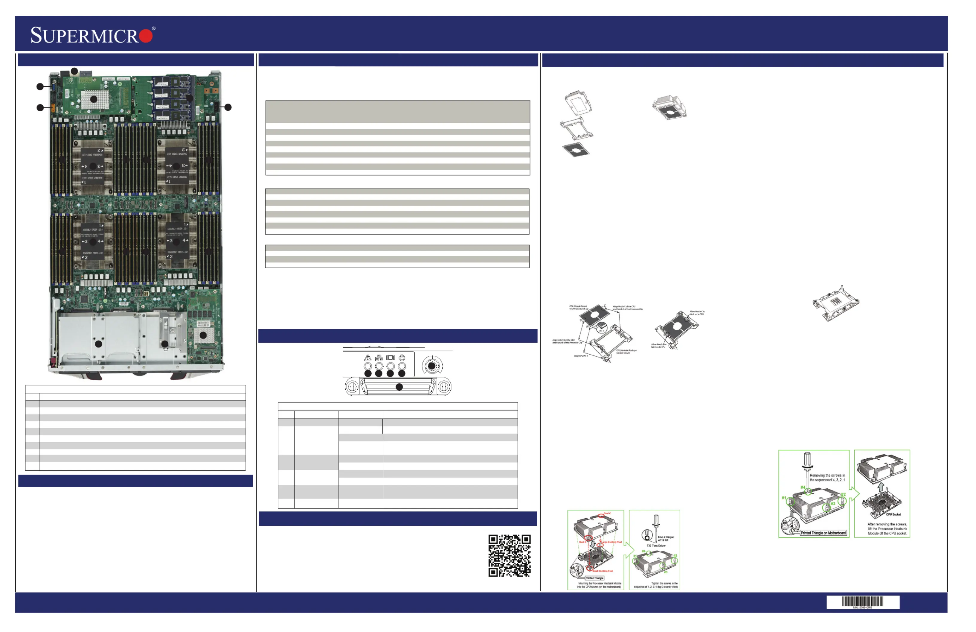
SuperBlade SBI-8149P-C4N/T8N Blade Module Quick Reference Guide
Memory Support
http://www.supermicro.com
MNL-2089-QRG
Rev 1.0
Board Layout
Supports up to 6 TB of RDIMM/3DS LRDIMM DDR4 2666 MHz speed and 8 GB, 16 GB, 32 GB, 64 GB and 128 GB size
SDRAM memory in forty-eight (48) 288-pin DIMM sockets for each node.
See https://www.supermicro.com/support/resources/memory/X11_memory_config_guide.pdf for details.
The Processor Heatsink Module (PHM) contains 1) a heatsink,
2) a narrow processor clip, and 3) the SKX(-F) processor.
1. Heatsink
2. Narrow Processor Clip
3. SKK Processor
Bottom View
Attaching the Processor to the Narrow Processor Clip to Create
the Processor Package Assembly
To properly install the CPU into the narrow processor clip, please follow
the steps below.
1. Locate pin 1 (notch A), which is the triangle located on the top of the
narrow processor clip. Also locate notch B and notch C on the processor clip.
2. Locate pin 1 (notch A), which is the triangle on the substrate of the CPU.
Also, locate notch B and notch C on the CPU as shown below.
3. Align pin 1 (the triangle on the substrate) of the CPU with pin 1 (the triangle)
of the narrow processor clip. Once they are aligned, carefully insert the CPU
into the processor clip by sliding notch B of the CPU into notch B of the
processor clip, and sliding notch C of the CPU into notch C of the processor clip.
4. Examine all corners of the CPU to ensure that it is properly seated on the
processor clip. Once the CPU is securely attached to the processor clip, the
processor package assembly is created.
Note: Please exercise extreme caution when handling the CPU. Do not touch the
CPU LGA-lands to avoid damaging the LGA-lands or the CPU. Be sure to wear
ESD gloves when handling components.
Attaching the Processor Package Assembly to the Heatsink to Form
the Processor Heatsink Module (PHM)
After you have made a processor package assembly by following the instructions on the
previous page, please follow the steps below to mount the processor package assembly
onto the heatsink to create the Processor Heatsink Module (PHM).
1. Locate "1" on the heatsink label and the triangular corner next to it on the heatsink.
With your index finger pressing against the screw at this triangular corner, carefully hold
and turn the heatsink upside down with the thermal-grease side facing up. Remove the
protective thermal film if present, and apply the proper amount of the thermal grease as
needed. (Skip this step if you have a new heatsink because the necessary thermal
grease is pre-applied in the factory.)
2. Holding the processor package assembly at the center edge, turn it upside down. With
the thermal-grease side facing up, locate the hollow triangle located at the corner of the
processor carrier assembly ("a" in the graphic). Note a larger hole and plastic mounting
clicks located next to the hollow triangle. Also locate another set of mounting clicks and a
larger hole at the diagonal corner of the same (reverse) side of the processor carrier
assembly ("b" in the graphic).
3. With the back of heatsink and the reverse side of the processor package assembly
facing up, align the triangular corner on the heatsink ("A" in the graphic) against the
mounting clips next to the hollow triangle ("a") on the processor package assembly.
4. Also align the triangular corner ("B") at the diagonal side of the heatsink with the
corresponding clips on the processor package assembly ("b").
5. Once the mounting clips on the processor package assembly are properly aligned with
the corresponding holes on the back of heatsink, securely attach the heatsink to the
processor package assembly by snapping the mounting clips at the proper places on the
heatsink to create the processor heatsink module (PHM).
Preparing the CPU Socket for Installation
This motherboard comes with the CPU socket pre-assembled in the factory. The CPU
socket contains 1) a dust cover, 2) a socket bracket, 3) the CPU (P0) socket, and 4) a
back plate. These components are pre-installed on the motherboard before shipping.
CPU Socket w/Dust Cover On
Removing the Dust Cover from the CPU Socket
Remove the dust cover from the CPU socket, exposing the SKX socket and socket pins
as shown on the illustration below.
Note: Do not touch the socket pins to avoid damaging them, causing the CPU to
malfunction.
Installing the Processor Heatsink Module (PHM)
Once you have assembled the processor heatsink module (PHM) by following the
instructions listed on page 29 or page 30, you are ready to install the processor
heatsink module (PHM) into the CPU socket on the motherboard. To install the PHM
into the CPU socket, follow the instructions below.
1. Locate the triangle (pin 1) on the CPU socket, and locate the triangle (pin 1) at the
corner of the PHM that is closest to "1." (If you have difficulty locating pin 1 of the
PHM, turn the PHM upside down. With the LGA-lands side facing up, you will note the
hollow triangle located next to a screw at the corner. Turn the PHM right side up, and
you will see a triangle marked on the processor clip at the same corner of hollow
triangle.)
2. Carefully align pin 1 (the triangle) on the PHM against pin 1 (the triangle) on the
CPU socket.
3. Once they are properly aligned, insert the two diagonal oval holes on the heatsink
into the guiding posts.
4. Using a T30 Torx-bit screwdriver, install four screws into the mounting holes on the
socket to securely attach the PHM onto the motherboard starting with the screw
marked "1" (in the sequence of 1, 2, 3, and 4).
Do not use excessive force when tightening the screws to avoid damaging the
LGA-lands and the processor.
Removing the Processor Heatsink Module (PHM) from the Motherboard
Before removing the processor heatsink module (PHM), unplug power cord from the
power outlet.
1. Using a T30 Torx-bit screwdriver, turn the screws on the PHM counterclockwise to
loosen them from the socket, starting with screw marked #4 (in the sequence of 4, 3, 2,
1).
2. After all four screws are removed, wiggle the PHM gently and pull it up to remove it
from the socket.
Note: To properly remove the processor heatsink module, be sure to loosen and remove
the screws on the PHM in the sequence of 4, 3, 2, 1 as shown below.
DDR4 Memory Support for Two Slots per Channel
Type Ranks DIMM Capacity (GB) Speed (MT/s)
Per DIMM Two Slots per Channel
and Data One DIMM per Channel Two DIMMs per Channel
Width 4 Gb 8 Gb 1.2 Volts 1.2 Volts
RDIMM SRx4 8 GB 16 GB 2666 2666
SRx8 4 GB 8 GB 2666 2666
DRx8 8 GB 16 GB 2666 2666
DRx4 16 GB 32 GB 2666 2666
RDIMM 3Ds QRX4 N/A 2H-64GB 2666 2666
8RX4 N/A 4H-128GB 2666 2666
LRDIMM QRx4 32 GB 64 GB 2666 2666
LRDIMM 3Ds QRX4 N/A 2H-64GB 2666 2666
8Rx4 N/A 4H-128 GB 2666 2666
SBI-8149P-C4N/T8NModuleLayout
ItemDescription
1 CPUs installed (four total)
2 Front housing for 2.5" SATA3/SSD/NVMe hard drive bays (four (C4N) or eight (T8N) total)
3 DIMM slots (48 total)
4 Power and Logic connectors to backplane
5 InfiniBand, Omni-path or NVMe/SATA Mezzanine Card
6 NVMe/SATA Mezzanine Card
7 Universal Serial Bus (3.0 USB) Ports
8 SATA DOM Port
9 9-pin TPM Connector
10 Broadcom 3108 Mezzanine Card
Key Parameters for DIMM Configurations
Parameters Possible Values
Number of Channels 1, 2, 3, 4, 5 or 6
Number of DIMMs per Channel 1DPC (1 DIMM Per Channel) or 2DPC (2 DIMMs Per Channel)
DIMM Type RDIMM (w/ECC), 3DS RDIMM, LRDIMM or 3DS-LRDIMM
DIMM Construction Non-3DS RDIMM Raw Cards: A/B (2RX4), C (1RX4), D (1RX8) or E (2RX8)
3DS RDIMM Raw Cards: A/B (4RX4)
Non-3DS LRDIMM Raw Cards: D/E (4RX4)
3DS LRDIMM Raw Cards: A/B (8RX4)
Mixing of DIMM Types within a Channel
DIMM Types RDIMM LRDIMM 3DS LRDIMM
RDIMM Allowed Not Allowed Not Allowed
LRDIMM Not Allowed Allowed Not Allowed
3DS LRDIMM Not Allowed Not Allowed Allowed
Control Panel
CPU and Heat Sink Installation
Caution
SAFETY INFORMATION
IMPORTANT: See installation instructions and safety warning before
connecting system to power supply.
http://www.supermicro.com/about/policies/safety_information.cfm
WARNING:
To reduce risk of electric shock/damage to equipment, disconnect power
from server by disconnecting all power cords from electrical outlets.
If any CPU socket empty, install protective plastic CPU cap
WARNING:
Always be sure all power supplies for this system have the same power
output. If mixed power supplies are installed, the system will not operate.
For more information go to: http://www.supermicro.com/support
!
!
!
InstallingtheProcessor
Enclosure Requirements
Enclosure Requirements
The SBI-8149P-C4N/T8N blade module requires one of the following enclosures to run in:
SBE-820C-822 SBE-820C-622 SBE-820C-422
SBE-820J-822 SBE-820J-622 SBE-820J-422
See the Supermicro webstite for details on enclosures at:
https://www.supermicro.com/en/products/superblade/enclosure
Note: The SBI-8149P-C4N/T8N blade module also requires one or more power supplies in the
enclosure to run the blade module. Available SuperBlade power supplies can be found on
the Supermicro website at https://www.supermicro.com/products/SuperBlade/powersupply/.
7
4
33
1
BladeControlPanel
ItemFunctionStateDescription
1PowerButtonN/A
2PowerLEDGreenIndicatespowerstatus“On”
SolidOrange
FlashingOrangeFlashingOrange:Indicatesnodeisnotreadyornotenough power to turn on
3KVM/UIDLEDBlueIndicatesKVMbeingutilizedonbladeunit
FlashingBlueIndicatesUIDactivatedonblademodule
4Network/IBLEDFlashingGreenIndicatesnetworkactivityoverLAN
FlashingOrangeIndicatesnetworkactivity
5
6
SystemFaultLED
KVM Connector
Red
N/A
Indicatesamemoryerror,overheat,VGAerrororanyerror
thatpreventsbooting
Connector for SUV/KVM cable
Indicates power status “Off” (with power cables plugged in)
Turns blade module on and off
5
22
10
1
2
345
6
8
6
9
33
3
3
33
1
11
Product specificaties
| Merk: | Supermicro |
| Categorie: | Server |
| Model: | SuperBlade SBI-8149P-C4N |
Heb je hulp nodig?
Als je hulp nodig hebt met Supermicro SuperBlade SBI-8149P-C4N stel dan hieronder een vraag en andere gebruikers zullen je antwoorden
Handleiding Server Supermicro

8 Februari 2026
8 Februari 2026
20 Januari 2026
20 Januari 2026
20 Januari 2026
20 Januari 2026
19 Januari 2026
19 November 2025
18 November 2025
1 Juli 2025
Handleiding Server
Nieuwste handleidingen voor Server
4 Mei 2026
14 April 2026
12 April 2026
11 April 2026
11 April 2026
10 April 2026
24 Maart 2026
24 Maart 2026
12 Maart 2026
2 Februari 2026