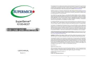
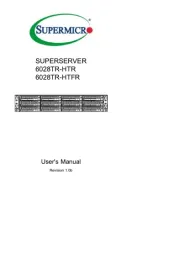
Supermicro A+ Server 2024US-TRT Handleiding
Supermicro
Server
A+ Server 2024US-TRT
Bekijk gratis de handleiding van Supermicro A+ Server 2024US-TRT (1 pagina’s), behorend tot de categorie Server. Deze gids werd als nuttig beoordeeld door 58 mensen en kreeg gemiddeld 4.5 sterren uit 29.5 reviews. Heb je een vraag over Supermicro A+ Server 2024US-TRT of wil je andere gebruikers van dit product iets vragen? Stel een vraag
Pagina 1/1

11 10 9
http://www.supermicro.com MNL-2315-QRG Rev. 1.0a
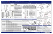
SuperServer AS -2024US-TRT Quick Reference Guide
Front View & Interface Rear View
Hard Drive Installation
Board Layout
Remov aing
Hot-Swap Drive Carrier from the
Chassis
1. Press the release button on the drive carrier, which will extend the
drive carrier handle.
2. Use the drive carrier handle to pull the drive out of the chassis.
Insta a Drivelling
1. Remove the dummy drive, by removing the screws securing the dummy drive to
the carrier. These screws are not used to mount the actual hard drive.
2. Insert a drive into the carrier with the PCB side facing down and the connector
end toward the rear of the carrier. Align the drive in the carrier so that the screw
holes line up.
3. Secure the drive to the carrier with four M3 screws, included in the chassis
accessory box.
4. Insert the drive carrier with the disk drive into its bay, keeping the carrier oriented
so that the release button is on the right side. When the carrier reaches the rear of
the bay, the release handle retracts.
5. Push the handle in until it clicks into its locked position.
Caution
SAFETY INFORMATION
IMPORTANT: See installation instructions and safety warning before
connecting system to power supply.
http://www.supermicro.com/about/policies/safety_information.cfm
WARNING:
To reduce risk of electric shock/damage to equipment, disconnect power
from server by disconnecting all power cords from electrical outlets.
If any CPU socket empty, install protective plastic CPU cap.
WARNING:
Always be sure all power supplies for this system have the same power
output. If mixed power supplies are installed, the system will not operate.
For more information go to : http://www.supermicro.com/support
!
!
!
1. Removing the Processor Force Frame
Use a Torx T20 driver to loosen the screws holding
down Force Frame in the sequence of . The 3-2-1
screw are numbered on the Force Frame next t each s o
screw hole.
2. Raising the Force Frame 3. Lifting the Rail Frame
5. Inserting the Carrier Frame/CPU Package 6. Lowering the Force Frame 7. Securing the Force Frame
Secure the screws in the order 1-2-3, tightening to
16.1 kgf-cm (14 lbf-in) of torque. The Force Frame
secures both the Rail Frame and CPU Package.
Caution: Tightening must be executed in proper
1-2-3 sequence to avoid causing catastrophic
damage to the socket or CPU Package.
8. The Force Frame Secured
Screw #1
Screw #2
Screw #3
Force Frame
Rail Frame
PnP Cover Cap
Carrier Frame/
CPU Package
Processor Installation
4. Removing the External Cap and PnP
Cover Cap
External Cap
PnP Cover Cap
Heatsink Installation
DescriptionNo.
1
2
3
4
5
6
7
8
9
PCI-E p1-x16 Slot (FH, 9.5” L)
PCI-E p1-x16 Slot (FH, 10.5” L)
VGA Port
UID LED
Serial Port
Dedicated LAN for IPMI
Two USB 3.0 Ports
Two 10G RJ45 Ports (Ultra Riser Card)
PCI-E p1-x16 Slot (LP)
10 PCI-E p1-x8 in p1-x16 Slot (FH, 10.5” L)
11 PCI-E p1-x16 Slot (FH, 10.5” L)
*Redundancy based on configuration and application load
Memory
DIMM Module Population Sequence
When installing memory modules, the DIMM slots should be populated in the following order:
DIMMA2, DIMMB2, DIMMC2, DIMMD2, DIMME2, DIMMF2, DIMMG2, DIMMH2, then DIMMA1,
DIMMB1, DIMMC1, DIMMD1, DIMME1, DIMMF1, DIMMG1, DIMMH1.
• The blue slots must be populated first.
• Always use DDR4 DIMM modules of the same type, size and speed.
• d DIMM s n be st d. er, l DI s Mixe speed ca in alle Howev al MM wil rul n a the d ot spee f stthe eslow DIMM.
• The motherboard will support odd-numbered modules (1 or 3 modules installed).
However, to achieve the best memory performance, fully populate the motherboard with validated
memory modules.
* Opt nal NVMeio Support (HDD0 a 1 from CPU1, a 3 from CPU2)nd HDD2 nd
1
2
HDD2
HDD1
HDD0
HDD5
HDD4
HDD3
HDD8
*
HDD7
HDD6
HDD11
*
HDD10
*
HDD9
*
3
4
7
6
58
9
10
12
RESET
Dummy Drive
Hard Drive Carrier
3
+
DESIGNED IN USA
H12DSU-iN
REV:
1 2
8
9
10
6
4 5
6
11 12 13 14 15 16
7
No. t nDescrip io
1SXB1 1 : -L s S t P PCI-E 4.0 )A/ B/1C WIO Ri er Card uppor (C U2 x32
2SXB2: S t P PCI-E 4.0 x )WIO-R Riser Card uppor (C U2 16
3SXB3 3 : t S t P PCI-E 4.0 )A/ B/3C Ul ra I/O Riser Card uppor (C U1 x40
4CPU1 NV 0- S A 7Me Ports 1, AT 0-
5S AAT DOM 3.0 98-
6CPU2 NV S A 3Me Port 0, AT 10-1
7CPU2 VNM e Port 1, S AAT 14-17
8CPU1 NV 3Me Ports 2-
9CPU2 NV 3Me Ports 2-
10 JBT1 - CMOS Clear
11 CPU2 DI A S tsMM 1-D2 lo
12 CPU2
13 CPU2 DI E otsMM 1-H2 Sl
14 CPU1 DI A S tsMM 1-D2 lo
15 CPU1
16 CPU1 DI E S tsMM 1-H2 lo
Pro o a Their Co o M escess rs nd rresponding Mem ry odul
CPU# Cha el nn
1Cha el nn
2Cha el nn
3Cha el nn
4Cha el nn
5Cha el nn
6Cha el nn
7Cha el nn
8
8 DI SMM
CPU1 C2 D2 G2 H2
CPU2 C2 D2 G2 H2
16 MM DI S
CPU1 A2 B2 C2 D2 E2 F2 G2 H2
CPU2 A2 B2 C2 D2 E2 F2 G2 H2
32 MM DI S
CPU1 A1 A2 B1 B2 C1 C2 D1 D2 E1 E2 F1 F2 G1 G2 H1 H2
CPU2 A1 A2 B1 B2 C1 C2 D1 D2 E1 E2 F1 F2 G1 G2 H1 H2
JL1
JF1
FAN7
FAN8JF2
P2-DIMMA1
P2-DIMMB1
P2-DIMMA2
P2-DIMMC1
P2-DIMMB2
P2-DIMMD2
P2-DIMMD1
P2-DIMMC2
JVR1
FAN3
FAN4
FAN5
FAN6
P2-DIMMH2
P2-DIMMG2
P2-DIMMH1
P2-DIMMF2
P2-DIMMG1
P2-DIMME2
P2-DIMMF1
P2-DIMME1
P1-DIMMD2
P1-DIMMC2
P1-DIMMC1
P1-DIMMD1
P1-DIMMA1
P1-DIMMA2
P1-DIMMB1
P1-DIMMB2
CPU1CPU2
P1-DIMMG1
P1-DIMMG2
P1-DIMMH1
P1-DIMMF2
P1-DIMMF1
P1-DIMME2
P1-DIMME1
P1-DIMMH2 FAN1
FAN2
LE1
CPU Installation
Hard Drive Signal
Hard Drive Fail
Power Button
Reset Button
NIC1 LED
Information LED
Power LED
NIC2 LED
DescriptionNo.
1
2
3
4
6
7
8
9
HDD Activity LED
Power Fail LED
5
10
83
6
745
12 1
Default Cable Routing
C or on onnect
Bo dar Card/ C n onn ioect
Backplane HDD Ba MC Ca y S bl P/e N
JSLIM1
(M -H12D U-iNB S ) CN1 CN 0- L-, 2 7 CB SAST-1253-100
JSLI 2M3-
(M -H12D U-iNB S ) CN 8-3 11 CB TL-SAS -1269 -10F 0
JSLIM2
(M -H12D U-iNB S ) NV 1Me 0-1
(Hybrid wi th S A)AT CB TL-SAS -1247-85
JSLIM4
(M -H12D U-iNB S ) NV 2Me 2-3
(Hybrid wi th S A)AT CB TL-SAS -1245-85
2
1
Redundant Power Supply Modules*
12
Removing a Drive Carrier
Release Button
1. Mounting the Heatsink 2. curing the HeatsinkSe
Using a diagonal pattern and a Torx T20 driver,
tighten the four heatsink screws evenly to 16.1
kgf-cm (14.0 lbf-in) torque.
#4 cre S w
#2 cre S w
#1 cre S w
#3 cre S w
Product specificaties
| Merk: | Supermicro |
| Categorie: | Server |
| Model: | A+ Server 2024US-TRT |
Heb je hulp nodig?
Als je hulp nodig hebt met Supermicro A+ Server 2024US-TRT stel dan hieronder een vraag en andere gebruikers zullen je antwoorden
Handleiding Server Supermicro
1 Juli 2025
13 Juni 2025
1 April 2025
30 Januari 2025

30 Januari 2025

8 Januari 2025

17 November 2024
17 November 2024
17 November 2024
17 November 2024
Handleiding Server
- Atlona
- Veritas
- Silex
- Planet
- Kathrein
- Nec
- Toshiba
- Cisco
- Maxdata
- IStarUSA
- Acer
- Atlantis Land
- ATen
- SilverStone
- Opengear
Nieuwste handleidingen voor Server
30 Juli 2025
30 Juli 2025
29 Juli 2025
29 Juli 2025
29 Juli 2025
29 Juli 2025
29 Juli 2025
29 Juli 2025
29 Juli 2025
29 Juli 2025