Sirius 3RV2011-0HA10 Handleiding
Sirius Famegmunkálás 3RV2011-0HA10
Bekijk gratis de handleiding van Sirius 3RV2011-0HA10 (8 pagina’s), behorend tot de categorie Famegmunkálás. Deze gids werd als nuttig beoordeeld door 95 mensen en kreeg gemiddeld 4.7 sterren uit 3 reviews. Heb je een vraag over Sirius 3RV2011-0HA10 of wil je andere gebruikers van dit product iets vragen? Stel een vraag
Pagina 1/8
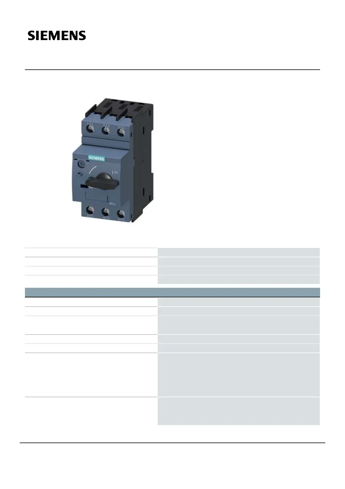
Data sheet3RV2011-0HA10
Circuit breaker size S00 for motor protection, CLASS 10 A-release
0.55...0.8 A N-release 10 A screw terminal Standard switching
capacity
Product brand nameSIRIUS
Product designationCircuit breaker
Design of the productFor motor protection
Product type designation3RV2
General technical data
Size of the circuit-breakerS00
Size of contactor can be combined company-specificS00, S0
Product extension
● Auxiliary switch
Yes
Power loss [W] total typical6W
Surge voltage resistance rated value6kV
maximum permissible voltage for safe isolation
● in networks with grounded star point between
main and auxiliary circuit
400V
● in networks with grounded star point between
main and auxiliary circuit
400V
Protection class IP
● on the front
IP20
● of the terminal
IP20
3RV2011-0HA10Subject to change without notice
Page 1/
8
06/07/2019© Copyright Siemens
Product specificaties
| Merk: | Sirius |
| Categorie: | Famegmunkálás |
| Model: | 3RV2011-0HA10 |
Heb je hulp nodig?
Als je hulp nodig hebt met Sirius 3RV2011-0HA10 stel dan hieronder een vraag en andere gebruikers zullen je antwoorden
Handleiding Famegmunkálás Sirius

28 Juni 2023
Handleiding Famegmunkálás
Nieuwste handleidingen voor Famegmunkálás
13 Juli 2026
13 Juli 2026
24 Februari 2026
2 September 2025
1 September 2025
5 Augustus 2025
5 Augustus 2025
4 Augustus 2025
4 Augustus 2025
4 Augustus 2025