SIIG CE-MT0612-S1 Handleiding

SIIG Flat panel steun CE-MT0612-S1

Lees hieronder de 📖 handleiding in het Nederlandse voor SIIG CE-MT0612-S1 (8 pagina's) in de categorie Flat panel steun. Deze handleiding was nuttig voor 19 personen en werd door 2 gebruikers gemiddeld met 4.5 sterren beoordeeld

Pagina 1/8
04-0528A
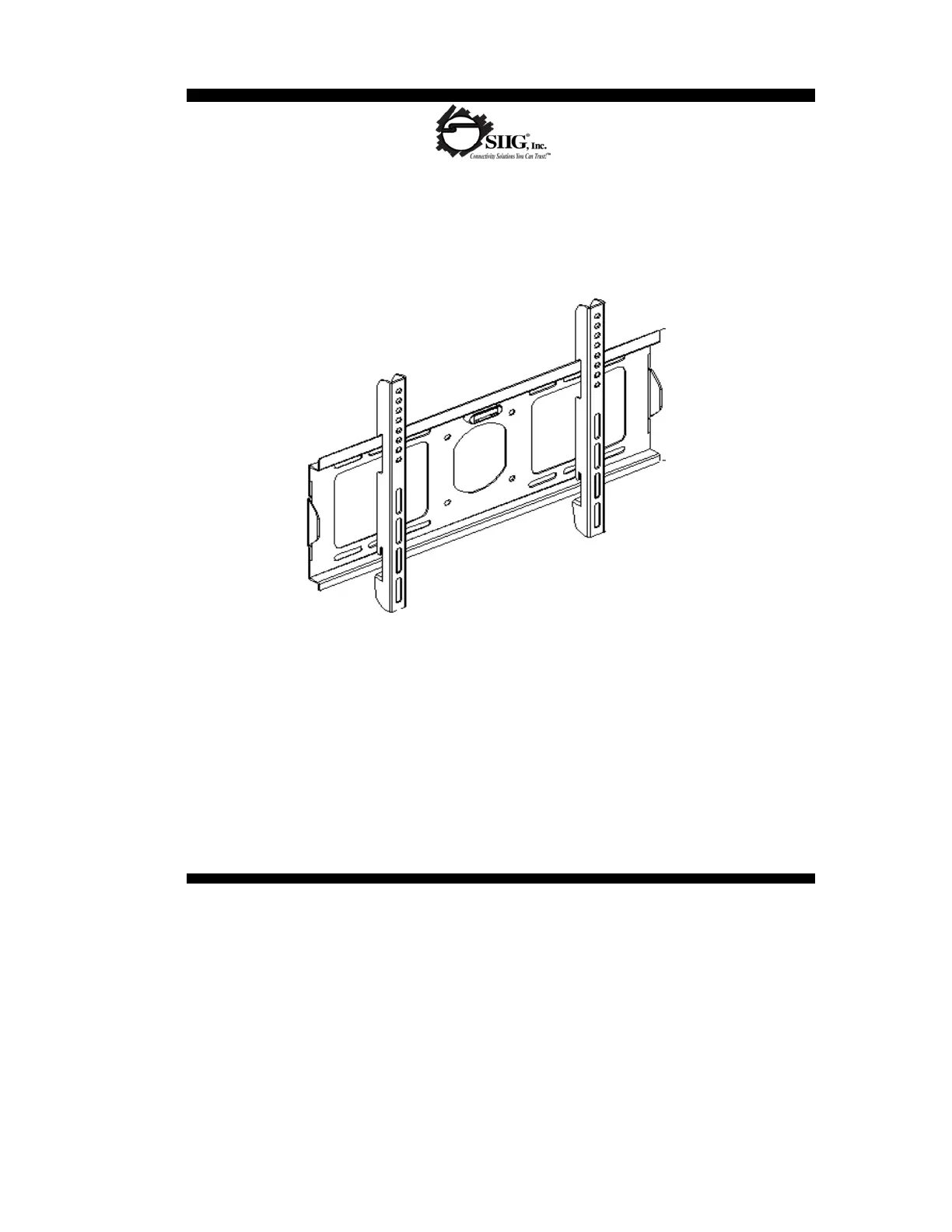
Low Profile Universal Mount - 32" to 60"
IMPORTANT: If you don't understand the installation instructions, please consult an installation
specialist
Fixed LCD/TFT TV Wall Mount
Material: 2.0mm Cold Rolled Steel Plate
TV Size: 32-60"
Max load capacity:165 lbs/75 kgs
Installation Instructions
Wall distance: 30mm/1.2"
Bubble level system included
Universal Mounting Pattern
A G
B H
C I
D J
E K
F L
M
(×4) M8 concrete anchor
(×4) M4×35 screw (×6) M8 Washer
(×4) M8 Spacer
(×4) M8×35 screw
The wall structure must be capable of supporting at least the maximum load capacity as indicated. If not, the wall must be
reinforced. Proper installation procedure by yourself or a qualified service technician, as outlined in the installation
instructions, must be adhered to. Failure to do so could result in serious personal injury.
Do not install near heater, fireplace, air conditioning, in direct sunlight, or any other heat producing source. Failure to do so
may result in damage to the display and could increase the risk of fire.
(×4) M4×12 screw
When mounting to a wall that contains wood studs, confirm dead center of the wood stud prior to installation, it is
recommended that the wood studs be a minimum of 16" apart.
(×4) M6×16 screw (×6) Bolt
(×4) M8×16 screw
INSTALLATION AND OPERATING INSTRUCTIONS
(×4) M6×35 screw
Caution
Hardware kit:
It is recommended that two people perform the installation. Injury and/or damage can result from dropping or mishandling
the display.
CAUTION: The maximum load capacity is 165 lbs. Use with products exceeding the maximum load capacity may cause
serious injury. See apparatus instructions.
(×4) M8/M6/M5 Washer
(×4) M4×16 screw
(×4) M5×16 screw
Do not install on a structure that is prone to vibration, movement or chance of impact. Failure to do so could result in
damage to the display and/or damage to the mounting surface.
Recommended mounting surfaces: wood stud and solid-flat concrete. If the mount is to be installed on any surface other
than wood studs, use suitable hardware (not included but commercially available).
Prior to the installation of this product, the installation instructions should be read and completely understood. The
installation instructions must be read to prevent personal injury and property damage. Keep these installation instructions
in an easily accessible location for future reference.
1
2
3
4
a) Wood Stud Installation
3
4
5
6
7
8
Stud finder for drywall installation
5/16" Socket and Wrench
Electric drill and 5/16" (8mm) masonry bit for concrete/brick installation
Note: Please ensure that the bubble level is mounted on the wall plate prior to mounting the wall plate.
Phillips head screw driver
CAUTION: Do not over-tighten bolts-doing so many cause unnecessary damage to the wall. Avoid excessive torque.
Mark the right (upper and lower) and the left (upper and lower) positions
of the small horizontalslots that are in alignment with the studs (figure 1
-
b).
CAUTION: Do not release the wall plate until it is properly mounted and secured to the wall.
Tools Required:
You should mark four positions total.
With the help of an assistant, and using the bubble level to ensure the
wall plate is level, position the wall plate against the wall in the desired
mounting location.
2
1
NOTE: When mounting to wood studs, the two wood studs must be a minimum of 16" apart.
Step1: Wall Plate Installation
Place the wall plate against the wall and line up the mounting slots with the drilled holes. Check the bubble level to verify
that the wall plate is level.
For each location, insert a lag bolt (J) and washer (L) into the wall
Tighten the bolt with an open ended socket wrench by turning clockwise until tight.
Use a high-quality electronic stud finder (commercially available) to
locate dead center of two studs and mark their locations with a pencil
(figure 1-a).
Next, pre-drill a 1/4" hole to a depth of 2" in the wall stud at each
marked location.


Product specificaties

Merk: SIIG
Categorie: Flat panel steun
Model: CE-MT0612-S1
Kleur van het product: Zwart
Gewicht: 3000 g
Breedte: 494 mm
Diepte: 820 mm
Hoogte: 300 mm
Montagewijze: Muur

Heb je hulp nodig?

Als je hulp nodig hebt met SIIG CE-MT0612-S1 stel dan hieronder een vraag en andere gebruikers zullen je antwoorden


Handleiding Flat panel steun SIIG

Handleiding Flat panel steun

Nieuwste handleidingen voor Flat panel steun