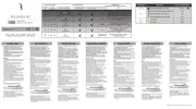
Shimano SM-3R40 Handleiding
Shimano
Fietsaccessoire
SM-3R40
Bekijk gratis de handleiding van Shimano SM-3R40 (1 pagina’s), behorend tot de categorie Fietsaccessoire. Deze gids werd als nuttig beoordeeld door 32 mensen en kreeg gemiddeld 4.9 sterren uit 16.5 reviews. Heb je een vraag over Shimano SM-3R40 of wil je andere gebruikers van dit product iets vragen? Stel een vraag
Pagina 1/1

SI-0123A-001-00
Important Safety Information
WARNING
● When installing components, be sure to follow the
instructions that are given in the instruction manuals. It is
recommended that you use only genuine Shimano parts.
If parts such as bolts and nuts become loose or damaged,
the bicycle may suddenly fall over, which may cause
serious injury.
In addition, if adjustments are not carried out correctly,
problems may occur, and the bicycle may suddenly fall
over, which may cause serious injury.
● After reading the instruction manual thoroughly, keep
it in a safe place for later reference.
● If you have any questions, consult a dealer or an
agency.
CAUTION
● Be sure to shift the lever one gear at a time, and
reduce the force being applied to the pedals during
shifting. If you try to force operation of the shifting
lever while the pedals are being turned strongly, your
feet may come off the pedals and the bicycle may
topple over, which could result in serious injury.
● Never place your foot on the bell crank. Otherwise,
gear shifting may not function properly.
Note:
For maximum performance p1-we highly recommend
Shimano lubricants and maintenance products.
Products are not guaranteed against natural wear and
deterioration from normal use and aging.
SI-0123A-001
REVOSHIFT Lever/
Bell Crank 4 /Bell Crank 6
(For internal 3-speed hubs)
Instructions for use
Be sure to read these technical service instructions in conjunction
with the technical service instructions for the Inter-3 hub.
REVOSHIFT lever operation
Turn the REVOSHIFT lever to shift one gear at a time.
REVOSHIFT lever
Indicator
Pedaling becomes heavier
Pedaling becomes lighter
Indicator moves toward 3
Indicator moves toward 1
…… Starting/Riding on sandy or rough road surfaces/Riding
up slopes/Carrying heavy loads/Riding into headwinds
……Riding on flat road surfaces
……Riding at high speeds
Installation of the lever
Install the lever as shown in the illustration.
22.2 mm
Tighten
Half grip
Clamp bolt
Handlebar
Brake lever
3 mm Allen key
Use a brake lever with a band width of 4.3 mm or lower so that
the brake lever does not interfere with the REVOSHIFT lever.
The straight section of the
handlebar must be 158 mm or
longer. The REVOSHIFT lever is
installed to this straight section.
1
2
3
4
Leave a clearance of 0.5 mm
between the REVOSHIFT lever and
the half grip.
Tightening torque:
2 - 2.5 N·m
{18 - 21 in. lbs.}
Installation of the shifting cable
Use a cable with one inner cable drum as the shifting cable.
Cassette joints side
Plastic cap
REVOSHIFT lever side
Plastic cap
1. Set the REVOSHIFT lever to 1.
Set to
1
■REVOSHIFT lever side
2. Loosen the two cover
fixing screws, and then
remove the cover.
Cover fixing screw
Cover fixing screw
Cover
Cover fixing screw
Top-fastening type
Bottom-fastening type
Note:
The cover is fastened from the top or bottom, depending on the
type being used.
Check the specifications and remove the cover accordingly.
3. Connect the inner cable to the connecting cable.
Hook the inner cable drum in the hole in the connecting
cable and insert the inner cable into the groove in the outer
holder.
Hole in the connecting cable
Groove in the outer holder
4. Fasten the cover with the two cover fixing screws.
Tightening torque:
0.1 - 0.2 N·m {0.9 - 1.7 in. lbs.}
Cover fixing screw
Cover fixing screw
Cover fixing screw
Top-fastening
Bottom-fastening type
Cover
Note:
The cover is fastened from the top or bottom, depending on the
type being used.
Check the specifications and attach the cover accordingly.
■Bell crank side
5. Loosen the cover fixing
screw, and then remove
the bell crank cover.
CHI NA
CHI NA
Cover fixing
screw
Bell crank
cover
6. Loosen the inner cable fixing nut on the main bell crank unit.
Next, pass the inner cable from the cable adjusting bolt
along the groove in the link and then in between the link
and the inner cable fixing plate.
CHINA
Link
Inner cable fixing plate
Inner cable fixing nut
Cable adjusting bolt
Loosen OK Not OK
Be sure to pass the inner cable
through the groove in the link.
7. Set the REVOSHIFT lever to 2.
Next, pull the inner cable so that the edges of the link on the
main bell crank unit are between the two yellow lines on the
window, and then tighten the inner cable fixing nut at that
position.
CHINA
Inner cable
fixing nut
Tighten
Pull
Yellow line Yellow line
Edge of link
The edges of the link should
be between the yellow lines.
After tightening the inner
cable fixing nut, cut off any
excess inner cable.
Within
4 mm
Tightening torque:
4 - 6 N·m {35 - 52 in. lbs.}
Set to
2
8. Replace the bell crank cover and tighten the cover fixing
screw.
Installation of bell crank
1. Insert the push rod
into the hub axle.
Push rod
The end of the push rod should project from the end of
the hub axle by approximately 14 mm.
Approx. 14 mm
2. While pushing the main bell crank unit onto the hub axle,
align the serrations inside the main bell crank unit with the
hub nut, and then push the main bell crank unit on until it
touches the end of the hub axle. In this position, tighten the
main unit installation bolt onto the hub axle.
Tightening torque:
3 - 5 N·m {27 - 43 in. lbs.}
S
ET
SET
Main unit
installation bolt
5 mm Allen key
or 10 mm
spanner
SET
SET
Hub nut
End of hub axle
Edge of window
The edge of the window and
the end of the hub axle
should be aligned.
Adjusting bell crank
1. Set the REVOSHIFT lever to 2.
Next, turn the cable adjusting bolt until the red line on the
push rod is aligned with the end of the hub axle.
SET
SET
Cable adjusting bolt
Push rod
Set to
2
The red line on the push rod and the end of the hub axle
should be aligned.
Yellow line
End of hub axle
Red line on push
rod
Yellow line
Yellow section
of link
If the red line on the push rod is not visible, adjust so that the
yellow section of the link is between the two yellow lines on
the window.
Note:
Look at the two yellow lines
from directly above during
adjustment.
2. While turning the crank arm, move the REVOSHIFT lever
from 3 to 1 and then from 1 back to 3 two or three times
to check the gear shifting.
Set the REVOSHIFT lever back to 2 and check that the red
line on the push rod is aligned with the end of the hub axle.
If they are not aligned, turn the cable adjusting bolt to
make fine adjustments.
3. After adjusting the
bell crank, tighten the
cable adjusting nut to
secure the cable
adjusting bolt.
SET
SET
Cable adjusting nut
Tightening torque:
1.5 - 2.5 N·m {14 - 21 in. lbs.}
Securing the shifting cable to the frame
Secure the cable to the frame with the outer casing bands.
20 – 25cm
Outer casing bands
There should be enough
slack so that the cable is not
pulled too much when the
handlebars are turned.
One Holland, Irvine, California 92618, U.S.A. Phone: +1-949-951-5003
Industrieweg 24, 8071 CT Nunspeet, The Netherlands Phone: +31-341-272222
3-77 Oimatsu-cho, Sakai-ku, Sakai-shi, Osaka 590-8577, Japan
* Service Instructions in further languages are available at:
http://si.shimano.com
Please note: Specifications are subject to change for improvement without
notice. (English)
© Apr. 2014 by Shimano Inc. HTR
Product specificaties
| Merk: | Shimano |
| Categorie: | Fietsaccessoire |
| Model: | SM-3R40 |
Heb je hulp nodig?
Als je hulp nodig hebt met Shimano SM-3R40 stel dan hieronder een vraag en andere gebruikers zullen je antwoorden
Handleiding Fietsaccessoire Shimano

15 November 2024

15 November 2024

12 Juni 2023

9 Juni 2023

8 Juni 2023

6 Juni 2023

4 Juni 2023

23 Mei 2023

22 Mei 2023

21 Mei 2023
Handleiding Fietsaccessoire
- MET Helmets
- Fiamma
- Blackburn
- Valk
- KLICKfix
- RockShox
- Cecotec
- Dnt
- Kayoba
- Hema
- Tacx
- Racktime
- Garmin
- MOTO
- Powerfix
Nieuwste handleidingen voor Fietsaccessoire

4 Augustus 2025

14 Juli 2025

14 Juli 2025

14 Juli 2025

4 Juli 2025

4 Juli 2025

4 Juli 2025

4 Juli 2025

4 Juli 2025

3 Juli 2025