RTS OKI Handleiding
Bekijk gratis de handleiding van RTS OKI (2 pagina’s), behorend tot de categorie Niet gecategoriseerd. Deze gids werd als nuttig beoordeeld door 111 mensen en kreeg gemiddeld 4.3 sterren uit 9 reviews. Heb je een vraag over RTS OKI of wil je andere gebruikers van dit product iets vragen? Stel een vraag
Pagina 1/2
Quick Start Guide
OKI - OMNEO Keypanel Interface KP 12 CLD
Included:
•OMNEOKeypanelModule
•RearPanel,KP12CLD,Expansion
•2-Screw,4-40x.25LG.
•3-Screw,PH,4-40x3/16LG.
•SafetyInstructionsST-CO
•OKIQuickStartGuide
•OKIDocumentationResourceDisk
Requirements:
Youmusthavethefollowing:
•PhillipsScrewdriver
•HexNutDriver
Firmware Requirements
•KP12CLDversion1.30
IMPORTANTThekeypanelrmwaremustbeupdatedbefore
youinstalltheOKImoduleintothekeypanel.
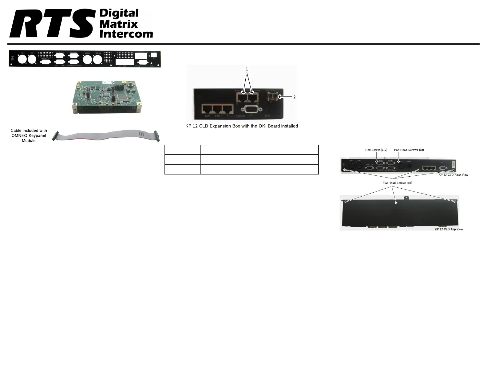
Reference View - OKI KP 12 CLD
Description
1.J1&J2RJ-45Connectors(2)
2.J3LCFiberConnector(Optional)
OKI Installation – KP 12 CLD
Toinstall the OKI board set for the KP 12 CLD,dothe
following:
NOTE:Becauseallthechangesaremadetothe
expansionbox,removetheexpansionboxfrom
theKP12CLDunit.
1.PowerofftheKP12CLDunit.
2.Removetheexpansion boxfromtheKP12CLD
unit.
NOTE:Steps3and4areonlynecessaryifanRCoption
isinstalled.
3.Usingahexnutdriver,removethe12 hex screws
fromtheKP12CLDexpansionbox.
4.Usingthesamescrewdriver,removetheeight (8)
pan head screwsfromtheKP12CLDexpansion
box.
5.UsingaPhillipsscrewdriver,removethesix (6) at
head screwsfrom KP12CLDexpansionbox.
F01U280811Rev0101/2013
Product specificaties
| Merk: | RTS |
| Categorie: | Niet gecategoriseerd |
| Model: | OKI |
Heb je hulp nodig?
Als je hulp nodig hebt met RTS OKI stel dan hieronder een vraag en andere gebruikers zullen je antwoorden
Handleiding Niet gecategoriseerd RTS

5 November 2025
5 November 2025
29 September 2025
29 September 2025
29 September 2025
29 September 2025
23 September 2025
15 September 2025
16 December 2024
11 December 2024
Handleiding Niet gecategoriseerd
Nieuwste handleidingen voor Niet gecategoriseerd
8 Juni 2026
8 Juni 2026
8 Juni 2026
8 Juni 2026
8 Juni 2026
8 Juni 2026
8 Juni 2026
8 Juni 2026
7 Juni 2026
7 Juni 2026