Rinnai RHFE-308FTR Handleiding

Rinnai Heater RHFE-308FTR

Lees hieronder de 📖 handleiding in het Nederlandse voor Rinnai RHFE-308FTR (28 pagina's) in de categorie Heater. Deze handleiding was nuttig voor 12 personen en werd door 2 gebruikers gemiddeld met 4.5 sterren beoordeeld

Pagina 1/28
To Suit Models:
RHFE-308FTR
RHFE-309FT
RHFE-556FTR
RHFE-556FDT
RHFE-557FTR
RHFE-559FT
RHFE-559FDT
RHFE-561FT
RHFE-1004FTR
RHFE-1004FDT
RHFE-1005FT
RHFE-1005FDT
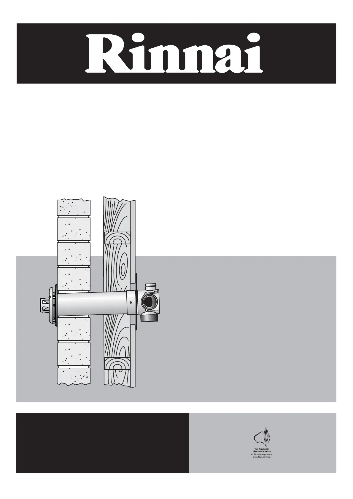
Energysaver Space Heater
Co-Axial Flue System
Installation Manual
These components shall be installed in accordance with:
• Manufacturer’s Installation Instructions
• Current AS/NZS 3000, AS/NZS 3500 & AS / NZS 5601
• Local Regulations and Municipal Building Codes
THESE COMPONENTS MUST BE INSTALLED, SERVICED AND REMOVED BY AN AUTHORISED PERSON!
ONLY THE FLUE SYSTEM COMPONENTS SPECIFIED IN THIS MANUAL MUST BE USED. COMPONENTS
NOT SPECIFIED IN THIS MANUAL, WHETHER MANUFACTURED BY RINNAI OR OTHERWISE, ARE NOT
COMPATIBLE AND “MUST NOT” BE USED!
The Rinnai EnergysaverÂŽ Co-Axial flue is certified as part of the
Rinnai Energysaver space heaters that have the designation ‘RHFE’ in
the model number .
Only an authorised person must install, service and remove the
Rinnai EnergysaverÂŽ space heater & flue system.
Only the flue system components described in this manual must be
used.
C o m p o n e n t s t h a t a r e n o t d e s c r i b e d i n t h i s m a n u a l , w h e t h e r
manufactured by Rinnai or otherwise, are not compatible and must
not be used. Rinnai appliance warranty conditions may be voided if
non Rinnai flue components are fitted.
Rinnai Australia i ES Flue Installation Manual
CONVENTIONS USED IN THIS MANUAL . . . . . . . . . . . . . . . . . . . . . . . . . . . . . . . . . . . . . . . . . . . . . . . . . . . . . . . . 1
REGULATIONS, CLEARANCES & GENERAL INFORMATION . . . . . . . . . . . . . . . . . . . . . . . . . . . . . . . . . . . . . . . 2
FLUE TRANSITION CONNECTIONS . . . . . . . . . . . . . . . . . . . . . . . . . . . . . . . . . . . . . . . . . . . . . . . . . . . . . . . . . . . . . . . . . . . .3
LOCATION . . . . . . . . . . . . . . . . . . . . . . . . . . . . . . . . . . . . . . . . . . . . . . . . . . . . . . . . . . . . . . . . . . . . . . . . . . . . . . . . . . . . . . . . .3
LUBRICATING INNER PIPE COMPONENTS. . . . . . . . . . . . . . . . . . . . . . . . . . . . . . . . . . . . . . . . . . . . . . . . . . . . . . . . . . . . . .3
INSTALLATION CONFIGURATIONS . . . . . . . . . . . . . . . . . . . . . . . . . . . . . . . . . . . . . . . . . . . . . . . . . . . . . . . . . . . . 4
WALL PENETRATIONS . . . . . . . . . . . . . . . . . . . . . . . . . . . . . . . . . . . . . . . . . . . . . . . . . . . . . . . . . . . . . . . . . . . . . . 6
FLUE KIT COMPONENTS . . . . . . . . . . . . . . . . . . . . . . . . . . . . . . . . . . . . . . . . . . . . . . . . . . . . . . . . . . . . . . . . . . . . 8
FLUE COMPONENT ASSEMBLY . . . . . . . . . . . . . . . . . . . . . . . . . . . . . . . . . . . . . . . . . . . . . . . . . . . . . . . . . . . . . . 9
CREATING A “DIRECT” FLUE INSTALLATION . . . . . . . . . . . . . . . . . . . . . . . . . . . . . . . . . . . . . . . . . . . . . . . . . . . . . . . . . . .9
CREATING A “DIRECT EXTENDED” FLUE INSTALLATION . . . . . . . . . . . . . . . . . . . . . . . . . . . . . . . . . . . . . . . . . . . . . . . . .9
CREATING AN “EXTERNAL WALL” FLUE INSTALLATION . . . . . . . . . . . . . . . . . . . . . . . . . . . . . . . . . . . . . . . . . . . . . . . .10
CREATING A “SIDEWAYS” FLUE INSTALLATION . . . . . . . . . . . . . . . . . . . . . . . . . . . . . . . . . . . . . . . . . . . . . . . . . . . . . . .13
CREATING AN “UNDER FLOOR” FLUE INSTALLATION . . . . . . . . . . . . . . . . . . . . . . . . . . . . . . . . . . . . . . . . . . . . . . . . . .14
CUTTING ~ ESDFK, ESPIPE900 & ESROOFCOWL . . . . . . . . . . . . . . . . . . . . . . . . . . . . . . . . . . . . . . . . . . . . . . . . . . . . . . .17
COMPONENT ASSEMBLY & CONNECTION ~ ESPIPE900 . . . . . . . . . . . . . . . . . . . . . . . . . . . . . . . . . . . . . . . . . . . . . . . . .17
ASSEMBLING WALL TERMINAL ~ ESDFK & ESPIPE900 . . . . . . . . . . . . . . . . . . . . . . . . . . . . . . . . . . . . . . . . . . . . . . . . . .18
ASSEMBLING AN ON-WALL TERMINAL ~ ESWTKIT, ESBEND & ESPIPE900 . . . . . . . . . . . . . . . . . . . . . . . . . . . . . . . . .18
COMPONENT ASSEMBLY & CONNECTION ~ ESBEND . . . . . . . . . . . . . . . . . . . . . . . . . . . . . . . . . . . . . . . . . . . . . . . . . . .19
COMPONENT ASSEMBLY AND CONNECTION ~ ESCONDK . . . . . . . . . . . . . . . . . . . . . . . . . . . . . . . . . . . . . . . . . . . . . . .19
COMPONENT ASSEMBLY & CONNECTION ~ ESROOFCOWL . . . . . . . . . . . . . . . . . . . . . . . . . . . . . . . . . . . . . . . . . . . . .19
CREATING AN “IN-WALL” FLUE INSTALLATION ~ ESFKIT03 & ESKITIW. . . . . . . . . . . . . . . . . . . . . . . . . . . . . . . . . . . .20
CONNECTING HEATER EXHAUST & AIR SUPPLY. . . . . . . . . . . . . . . . . . . . . . . . . . . . . . . . . . . . . . . . . . . . . . . 23
CONNECTING HEATER EXHAUST . . . . . . . . . . . . . . . . . . . . . . . . . . . . . . . . . . . . . . . . . . . . . . . . . . . . . . . . . . . . . . . . . . . .23
CONNECTING COMBUSTION AIR HOSE (AIR SUPPLY). . . . . . . . . . . . . . . . . . . . . . . . . . . . . . . . . . . . . . . . . . . . . . . . . . .24
CONNECTING CONDENSATE DRAIN TUBE TO HEATER . . . . . . . . . . . . . . . . . . . . . . . . . . . . . . . . . . . . . . . . . 25
CONTACT INFORMATION . . . . . . . . . . . . . . . . . . . . . . . . . . . . . . . . . . . . . . . . . . . . . . . . . . . . . . . . . . . . . . . . . . 26
TABLE OF CONTENTS
Rinnai Australia 1 ES Flue Installation Manual
CONVENTIONS USED IN THIS MANUAL
The following symbols are used to highlight specific requirements during installation steps.
The heater and the flue system shall be installed in accordance with the following:
CLEARANCES
Where required clearances will be provided and must be observed.
FALL
Ensure that the specified 2° fall is maintained to either the terminal or condensate trap.
MEASURE
Required measurements will be provided and MUST BE observed for correct installation.
CUT
Cut as required to the specified measurements.
FINISH
Ensure that burrs and swarf are removed from all cut ends.
DISCARD
Denotes items that are not required for the specific installation.
OBSERVE CORRECT ORIENTATION
Where specified ensure that components are installed with the correct vertical or horizontal
orientation.
LUBRICATE
Use the supplied container of silicon grease to lubricate components. DO NOT use other
lubricants as these may damage the flue components.
SECURE
Where specified secure components with either installer provided or component supplied fixings.
DO NOT
Failure to observe DO NOT instructions will void the warranty of an appliance and may cause
injury or death.
NOTE / IMPORTANT
Important notes or general hints and guides provided to ease the installation.
CAUTION
Caution notes and or warnings that MUST BE observed for safe and correct installations.
!
!


Product specificaties

Merk: Rinnai
Categorie: Heater
Model: RHFE-308FTR

Heb je hulp nodig?

Als je hulp nodig hebt met Rinnai RHFE-308FTR stel dan hieronder een vraag en andere gebruikers zullen je antwoorden


Handleiding Heater Rinnai

Handleiding Heater

Nieuwste handleidingen voor Heater