Rikon 30-230 Handleiding
Rikon Boormachine 30-230
Bekijk gratis de handleiding van Rikon 30-230 (24 pagina’s), behorend tot de categorie Boormachine. Deze gids werd als nuttig beoordeeld door 78 mensen en kreeg gemiddeld 4.5 sterren uit 9 reviews. Heb je een vraag over Rikon 30-230 of wil je andere gebruikers van dit product iets vragen? Stel een vraag
Pagina 1/24
www.rikontools.com
30-230M6
Operator’s Manual
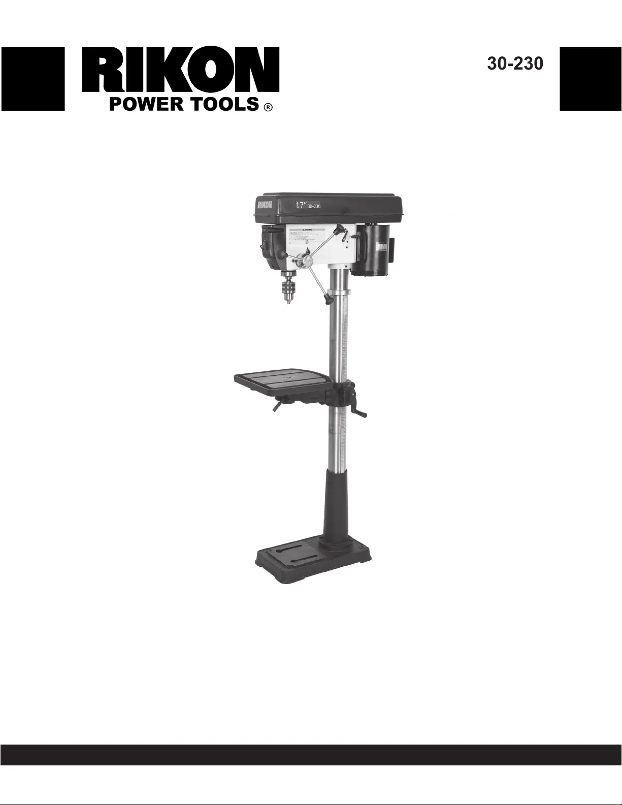
30-230
17” Floor Drill Press
Record the serial number and date of purchase in your manual for future reference.
Serial Number: _________________________ Date of purchase: _________________________
For technical support or parts questions, email [email protected] or call toll free at (877) 884-5167
The serial number can be found on the specication label on the rear of your machine.
Product specificaties
| Merk: | Rikon |
| Categorie: | Boormachine |
| Model: | 30-230 |
Heb je hulp nodig?
Als je hulp nodig hebt met Rikon 30-230 stel dan hieronder een vraag en andere gebruikers zullen je antwoorden
Handleiding Boormachine Rikon

18 November 2024
18 November 2024
18 November 2024
18 November 2024
18 November 2024
18 November 2024
5 Januari 2024
Handleiding Boormachine
Nieuwste handleidingen voor Boormachine
22 April 2026
20 April 2026
11 April 2026
11 April 2026
6 April 2026
3 April 2026
30 Maart 2026
30 Maart 2026
30 Maart 2026
30 Maart 2026