NuTone 8663RP Handleiding
NuTone
Ventilator
8663RP
Bekijk gratis de handleiding van NuTone 8663RP (12 pagina’s), behorend tot de categorie Ventilator. Deze gids werd als nuttig beoordeeld door 4 mensen en kreeg gemiddeld 4.4 sterren uit 2.5 reviews. Heb je een vraag over NuTone 8663RP of wil je andere gebruikers van dit product iets vragen? Stel een vraag
Pagina 1/12

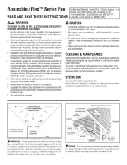
READ & SAVE THESE INSTRUCTIONS!
INSTALLATION INSTRUCTIONS
Ventilation Fan
with Light
Suitable for use in insulated ceilings.
WARNING: To reduce the risk of fire or electrical shock, do not use this
fan with any solid-state speed control device. Do not install in a ceiling
insulated to a value greater than R-40.
IMPORTANT SAFETY INSTRUCTIONS
WARNING – TO REDUCE THE RISK OF FIRE, ELECTRIC SHOCK, OR
INJURY TO PERSONS, OBSERVE THE FOLLOWING:
A. Use this unit only in the manner intended by the manufacturer.
If you have questions, contact the manufacturer.
B. Before servicing or cleaning unit, switch power off at Service Panel and
lock Service Panel to prevent power from being switched on accidentally.
When the service disconnecting means cannot be locked, securely fas-
ten a prominent warning device, such as a tag, to the service panel.
CAUTION:
For general ventilating use only. Do not use to exhaust hazardous or
explosive materials and vapors.
INSTALLATION INSTRUCTIONS
WARNING – TO REDUCE THE RISK OF FIRE, ELECTRIC SHOCK, OR
INJURY TO PERSONS, OBSERVE THE FOLLOWING:
A. Installation work and electrical wiring must be done by qualified person(s)
in accordance with all applicable codes and standards, including fire-rated
construction.
B. Sufficient air is needed for proper combustion and exhausting of gases
through the flue (chimney) of fuel burning equipment to prevent back
drafting. Follow the heating equipment manufacturer’s guideline and
safety standards such as those published by the National Fire Protection
Association (NFPA),
and the American Society for Heating, Refrigeration and Air Conditioning
Engineers (ASHRAE), and the local code authorities.
C. When cutting or drilling into wall or ceiling, do not damage electrical wiring
and other hidden utilities.
D. Ducted fans must always be vented to the outdoors.
E. If this unit is to be installed over a tub or shower, it must be marked as
appropriate for the application.
F. NEVER place a switch where it can be reached from a tub or shower.
G.
For installation in sloped ceilings up to 12/12 pitch.
H.
Ductwork must point up.
FOR BEST RESULTS
When installing the Exhaust Fan/Light in a new construction site, install
housing during the rough-in construction of the building. The blower unit,
reflector and grille should be installed after the finished ceiling is in place.
-Refer to instructions on page 3 to install the Exhaust Fan/Light in an exist
ing finished building.
PLANNING DUCTWORK AND WIRING
1. Use 4” round duct.
2. Plan duct run from discharge opening of fan to the outside. For best fan
performance, make duct run as short as possible and use minimum num-
ber of elbows.
3. Use optional NuTone ducting accessories as needed.
MODEL: 8663RP, 8664RP
Suitable for use in shower or tub enclosure when used
with GFI protected branch circuit.
IMPORTANT: Use wire suitable for 90°C.
Plan to run 120vAC house wiring (with ground) from power source, through
wall switches, to junction box in fan. For separate control of fan, light, and
night light three wall switches are required. See NuTone Catalog for accesso-
ry switches. For separate control of fan, light, and night light, five conductors
are needed between the wall switch box and the fan’s junction box. (Night
light not provided on 8664RP).
INSTALLATION IN A NEW
CONSTRUCTION SITE
PREPARATION
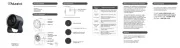
1. Refer to Figure 1. Remove power unit/blower assembly from housing.
A. Unplug power unit.
B. Remove screw (located next to plug-in receptacle) which holds power/
blower unit mounting plate in place. Save screw.
C. Lift mounting plate at end near the plug-in receptacle until blower
wheel clears the scroll.
D. Remove plate by pulling its tabs out of slots in housing. Set power/
blower unit aside until needed.
2. Remove one of the wiring knockouts from housing.
Wiring
Knockouts
FIGURE 1
Housing
Scroll
Slots
Power/Blower
Unit
Reflector
Assembly
Night Light
Socket
(not provided
on 8664RP)
Acorn Nut
Grille/Lens
Assembly
Mounting
Springs (2)
Duct
Collar
Tabs
TO REGISTER THIS PRODUCT, VISIT WWW.NUTONE.COM
Hanger Bars

FIGURE 4B
120 VAC
FAN
SWITCH
LIGHT
SWITCH
8664RP
FAN
RECEPTACLE
LIGHT
RECEPTACLE
WHITE
B
L
K
B
L
U
G
R
O
U
N
D
FIGURE 4A
FAN
RECEPTACLE
LIGHT
RECEPTACLE
FAN
SWITCH
LIGHT
SWITCH
NIGHT
LIGHT
SWITCH
120 VAC
WHITE
Y
E
L
L
O
W
R
E
D
B
L
K
8663RP
G
R
O
U
N
D
MOUNTING THE HOUSING
Note: When installing in existing construction, refer to page 3
Mounting Using Mounting Tabs
Refer to Figure 2.
1. Locate fan housing next to ceiling joist.
2. Use wood screws (not provided) to loosely attach housing to ceiling joist
through keyhole slots in mounting tabs.
3. Adjust housing so that it will be flush with finished ceiling. For the grille to fit
properly, the housing’s rim must not extend beyond finished ceiling surface.
4. When housing is properly adjusted, tighten screws in slots.
Mounting Using Hanger Bars
Refer to Figure 3.
1. Insert hanger bars in slots provded in housing.
2. Locate fan housing between joists so that the bottom of the housing is even
with the planned finished ceiling.
3. Use screws or nails (not provided) to secure hanger bars to ceiling joists.
INSTALLING DUCTWORK
1. Refer to Figure 1. Place duct collar over flanges at discharge opening of fan.
Secure collar by snapping tabs into slots in flanges.
2. Run 4” round duct from fan’s discharge opening to the outside and terminate.
WIRING
All wiring must comply with local codes and unit must be properly ground-
ed.
IMPORTANT: Use wire suitable for 90°C.
1. Run 120vAC house wiring from wall switches to fan location, neutral (white),
ground (bare copper), and three switched hot leads. See Figure 4.
2. Insert and secure an approved box connector into wiring entrance hole.
3. Pull wires through box connector and into junction box. Tighten box connector.
4. Refer to Figure 4A. (For 8663RP)
Connect white wires from the fan and light receptacles to white (neutral) wire
from the supply. Connect black wire to wire from fan switch. Connect red wire
to wire from light switch. Connect yellow wire to wire from night light switch.
Refer to Figure 4B. (For 8664RP)
Connect white wires from the fan and light receptacles to white (neutral) wire
from the supply. Connect black wire from fan (BLK) receptacle to wire from fan
switch. Connect blue from light (WH) receptacles to wire from light switch.
5. Connect the green (or bare) ground wire to the green ground lead.
FIGURE 2
Duct Collar
Flanges
Wiring
Knockouts
Mounting
Tabs
Bottom
Rim

POWER/BLOWER UNIT INSTALLATION
1. Refer to Figure 1. Place power/blower unit into housing so that mounting
plate’s tabs insert into slots in housing.
2. Press other end of mounting plate down until it is firmly seated over scroll
and plug-in receptacles.
3. Secure mounting plate to housing with provided screw.
4. Insert motor plug into junction box receptacle.
COMPLETING INSTALLATION
1. Insert lamp plug into junction box receptacle and secure reflector assembly to
motor frame with wing nut provided.
2. Install lamps 100 watt (maximum) for light, and 7 watt (maximum) for
night light (Night light not provided on 8664RP).
3. Squeezing the grille assembly’s mounting springs together, insert springs into
slots on both sides of housing.
4. Press grille assembly firmly into place against ceiling.
INSTALLATION IN EXISTING CONSTRUCTION
Locate fan between ceiling joists.
Plan ducting wiring before proceeding with installation. Refer to Figure 4 for
wiring. CAUTION: Check area above planned location to be sure that:
1. Ducting can be installed.
2. Wiring can be run to the planned location.
3. No wiring or other obstruction might interfere with installation.
INSTALLATION FROM ACCESSIBLE AREA ABOVE
1. After determining desired location for fan, drill a small hole in the ceiling.
Place a coat hanger or other stiff wire up through hole to help in locating from
above.
2. Place fan housing on top of ceiling surface and use the housing as a
template to mark area to be cut out. Cut round hole 13
1
⁄8” in diameter for
rough opening.
3. After cutting out opening, mount housing in the opening using the hanger
bars provided.
A. Insert hanger bars in slots in housing.
B. Position housing in opening so that bottom of housing is flush with ceiling.
C. Use screws or nails (not provided) to secure hanger bars to ceiling joists.
4. Install ducting and wiring as described above.
INSTALLATION FROM AREA BELOW CEILING
Note: If you do not have access to the area above the installation location, make
sure that the installation will not interfere with existing wiring, plumbing, etc. and
that the wiring and ducting can be run to the desired location. It will be neces-
sary to use flexible duct when installing the unit from below.
1. The fan must be mounted between ceiling joists. Decide where you want to
locate the fan, and then determine where the nearest joists are.
Locating Joists – Lightly tap the ceiling. A hollow sound means no joist; a
solid sound means a joist is present. To be sure you have located a joist, drill
a small hole (1/16”) and probe into the ceiling with a wire.
2. Locate the joists. Drill a starter hole in the ceiling between the joists.
3. To exactly locate the edge of joist, saw a line from hole to joist.
4. Refer to page 1. Remove power/blower unit from housing.
5. Use the housing pan as a template to mark cutout: place pan centered
between joist and trace around pan.
6. Make cutout along outside of marked line.
7. Refer to Figure 5. Install 2 x 4 cleats to both ceiling joists. In some cases it
may be necessary to use more than a single cleat on one side. The distance
between cleats must be at least 9
1
⁄8” but not more than 10”.
8. Remove side wiring knockout and insert and secure an approved box con-
nector into the wiring entrance hole.
9. Use pliers to bend both mounting tabs as flush as possible to the side of the
housing.
10. Install duct collar.
11. String wiring through box connector and connect 4” flexible duct to duct col-
lar.
12. Carefully push ductwork and wiring back into cutout. Place housing into
cutout.
13. Use wood screws to secure housing to cleats through four holes in hous-
ing’s pan. Make sure pan is flush to finished ceiling.
14. Install Power/Blower Unit and complete installation.
FIGURE 5
FIGURE 6
11-1/2”
9-1/8 10””-
Joist
2”
4”
5-3/4”
4” Flexible
Duct
120vAC
House Wiring
Duct
Collar
Wiring
Knockout
Bend
Mounting
Tabs
Flush To
Side of
Housing
Mounting
Holes
CLEANING AND RELAMPING
1. Pull grille assembly away from ceiling.
2. Squeezing the grille assembly’s mounting springs together, remove grille
assembly from housing to expose socket for relamping.
3. Clean grille and lens assembly using a mild soap and water solution.
Assemblies with wood frames should not be immersed.
4. Replace grille assembly flat against ceiling after cleaning or relamping.
Cleat
Product specificaties
| Merk: | NuTone |
| Categorie: | Ventilator |
| Model: | 8663RP |
Heb je hulp nodig?
Als je hulp nodig hebt met NuTone 8663RP stel dan hieronder een vraag en andere gebruikers zullen je antwoorden
Handleiding Ventilator NuTone
17 April 2025
16 April 2025
16 April 2025
16 April 2025

16 April 2025
16 April 2025

16 April 2025

16 April 2025

16 April 2025

16 April 2025
Handleiding Ventilator
- Heylo
- O2 Cool
- Team
- Primo
- Honeywell
- Meaco
- Airis
- Salco
- Svan
- Hema
- Helios
- Andrews
- Kemot
- Infiniton
- Arcoaire
Nieuwste handleidingen voor Ventilator
16 September 2025
15 September 2025
15 September 2025
15 September 2025
15 September 2025
15 September 2025
15 September 2025
15 September 2025
13 September 2025
12 September 2025