NuTone 763H Handleiding
NuTone
Ventilator
763H
Bekijk gratis de handleiding van NuTone 763H (4 pagina’s), behorend tot de categorie Ventilator. Deze gids werd als nuttig beoordeeld door 7 mensen en kreeg gemiddeld 5.0 sterren uit 4 reviews. Heb je een vraag over NuTone 763H of wil je andere gebruikers van dit product iets vragen? Stel een vraag
Pagina 1/4

1
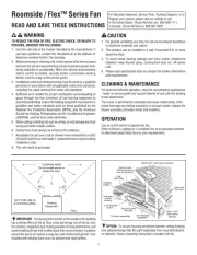
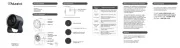
FAN/LIGHT COMBINATION VENTILATORS
MODELS 763 • 763N
WARNING
TO REDUCE THE RISK OF FIRE, ELECTRIC SHOCK, OR INJURY TO
PERSONS, OBSERVE THE FOLLOWING:
1. Use this unit only in the manner intended by the manufacturer. If you
have questions, contact the manufacturer at the address or telephone
number listed in the warranty.
2. Before servicing or cleaning unit, switch power off at service panel and
lock the service disconnecting means to prevent power from being
switched on accidentally. When the service disconnecting means cannot
be locked, securely fasten a prominent warning device, such as a tag,
to the service panel.
3. Installation work and electrical wiring must be done by a qualifi ed
person(s) in accordance with all applicable codes and standards, including
fi re-rated construction codes and standards.
4. Suffi cient air is needed for proper combustion and exhausting of gases
through the fl ue (chimney) of fuel burning equipment to prevent back-
drafting. Follow the heating equipment manufacturer’s guideline and
safety standards such as those published by the National Fire Protection
Association (NFPA), and the American Society for Heating, Refrigeration
and Air Conditioning Engineers (ASHRAE), and the local code authorities.
5. When cutting or drilling into wall or ceiling, do not damage electrical
wiring and other hidden utilities.
6. Ducted fans must always be vented to the outdoors.
7. If this unit is to be installed over a tub or shower, it must be marked
as appropriate for the application and be connected to a GFCI (Ground
Fault Circuit Interrupter) - protected branch circuit.
8. Never place a switch where it can be reached from a tub or shower.
9. This unit must be grounded.
READ AND SAVE THESE INSTRUCTIONS
TYPICAL INSTALLATIONS
HOUSING
CEILING
JOIST
MOUNTING TABS
GRILLE
CEILING
MATERIAL
POWER CABLE
HOUSING
CEILING
JOIST
MOUNTING TABS
GRILLE
CEILING
MATERIAL
POWER CABLE
4" ROUND
DUCT
ADDITIONAL
FRAMING
HOUSING MOUNTED TO ADDITIONAL FRAMING
Discharge 90 to joists.
HOUSING MOUNTED DIRECTLY TO JOIST
2 x 6 (or larger)
Discharge parallel to joists.
HOUSING
2 x 4
CEILING
JOIST or
TRUSS
MOUNTING
TABS
CEILING
MATERIAL
POWER CABLE
ADDITIONAL
FRAMING
2 x 4
CEILING
JOIST or
TRUSS
GRILLE
HOUSING MOUNTED TO 2 x 4 TRUSS
Requires additional framing
for mounting tabs.
Discharge parallel to joists.
HOUSING
2 x 4
CEILING
JOIST or
TRUSS
MOUNTING TABS
CEILING
MATERIAL
POWER CABLE
4" ROUND
DUCT
ADDITIONAL
FRAMING
2 x 4
CEILING
JOIST or
TRUSS
GRILLE
HOUSING MOUNTED TO 2 x 4 TRUSS
Requires additional framing for mounting tabs.
Discharge 90 to joists.
HOUSING
MOUNTING TABS
CEILING
MATERIAL
POWER CABLE
4" ROUND
DUCT
ADDITIONAL
FRAMING
"
I
"
JOIST
"
I
"
JOIST
GRILLE
HOUSING MOUNTED TO “I” JOIST
Requires additional framing for mounting tabs.
Discharge 90 to joists.
*Additional framing must be a 2 x 6
(minimum height).
*
*
*
*
HOUSING
MOUNTING
TABS
CEILING
MATERIAL
POWER CABLE
ADDITIONAL
FRAMING
"
I
"
JOIST
"
I
"
JOIST
GRILLE
HOUSING MOUNTED TO “I” JOIST
Requires additional framing
for mounting tabs.
Discharge parallel to joists.
*
USE AND CARE
WARNING: DISCONNECT ELECTRICAL POWER SUPPLY AND LOCK OUT SERVICE
PANEL BEFORE CLEANING OR SERVICING THIS UNIT.
BULB REPLACEMENT
Remove lens by gently depressing sides and pull down.
Use 100 Watt maximum incandescent bulb.
MOTOR LUBRICATION
The motor is permanently lubricated. Do not oil or disassemble motor.
CLEANING
TO CLEAN LENS AND GRILLE:
Remove light lens and bulb. Remove nut in center of refl ector and lower assembly.
CAUTION: Grille and re ector are separate units. Unplug light from WHITE receptacle.
Plastic parts can be cleaned with mild, soapy water (use a mild detergent, such
as dishwashing liquid) and dried with a soft cloth. Do not use abrasive cloth, steel
wool pads, or scouring powders.
TO CLEAN FAN ASSEMBLY:
Unplug fan assembly (BLACK receptacle). To remove motor plate: Find the single tab on the
motor plate (located next to the receptacles). Push up near motor plate tab while pushing
out on side of housing. Or insert a straight-blade screwdriver into slot in housing (next to
tab) and twist screwdriver. Gently vacuum fan, motor and interior of housing. METAL AND
ELECTRICAL PARTS SHOULD NEVER BE IMMERSED IN WATER.
!
CAUTION
1. For general ventilating use only. Do not use to exhaust hazardous or
explosive materials and vapors.
2. This product is designed for ceiling installation only. This product is
designed for installation in ceilings up to a 12/12 pitch. Ductwork must
point up. DO NOT MOUNT THIS PRODUCT IN A WALL.
3. To avoid motor bearing damage and noisy and/or unbalanced impellers,
keep drywall spray, construction dust, etc. off power unit.
4. Please read specifi cation label on product for further information and
requirements.
Installer: Leave this manual with the homeowner.
MOUNTING
TAB
GRILLE
SUSPENDED
CEILING MATERIAL
POWER
CABLE
4" ROUND
DUCT
HOUSING
SUSPENDED CEILINGS
Housing hung with wires - 3-point mount.
1100475C

2
INSTALL THE HOUSING
- PLEASE NOTE -
THE FOLLOWING INSTALLATION ILLUSTRATIONS SHOW 2 X 6
JOISTS. IF YOU HAVE A TRUSS OR “I”-JOIST INSTALLATION,
MOUNT THE VENTILATOR TO THE ADDITIONAL FRAMING IN
THE SAME MANNER. (Additional framing must be a 2 x 6
(minimum height).
1. Choose the location for your fan in the ceiling. For best
possible performance, use the shortest possible duct run
and a minimum number of elbows.
2. Position mounting
brackets against joist
so that bottom edge of
housing will be fl ush
with fi nished ceiling.
Additional positioning
feature for 5/8”, 1”,
& 1-1/4” thick ceiling
material:
Holes in corners of
housing are labeled with various ceiling material thicknesses.
Position housing so bottom edge of joist is visible through
a matched set of holes. The housing is now in the proper
position for that ceiling material thickness.
Additional positioning feature for 1/2” thick ceiling
material:
Bend two tabs, on side of housing,
90° outward. Lift housing
until tabs contact underside of joist.
Mark the keyhole slot on both mounting brackets.
New Construction
5/8
1
1-1/4
TAB
HOLES
BOTTOM EDGE OF JOIST
3. Set housing aside and
drive nails partially into
joist at the top of both
keyhole marks.
4. Hang housing from nails
and pound nails tight.
To ensure a noise-free
mount, pound another
nail through the top hole
of each mounting tab.
4. Place housing in opening so that its bottom edge
is fl ush with fi nished ceiling. Nail to joist through
keyhole on both sides. To ensure a noise-free
installation, drive another nail through the top hole
of each mounting bracket.
5. Additional mounting holes are provided for
installations where access from above is
inconvenient or not possible. Nail or screw
housing directly to joists or framing.
INSTALL THE HOUSING (cont’d)
INSTALL THE DUCTWORK
NOTE: The duct connector has a counter-balanced
damper fl ap. The fl ap will be “open” approx. 1” when
duct connector is attached to housing. This design
permits insulation to be in direct contact with fan/light
housing per UL (Underwriters Laboratories) standards.
The slightest backdraft, however, will close the damper
fl ap, preventing air from entering unit or fi nished space.
1. Snap the damper/duct connector onto housing.
Make sure that tabs on the connector lock into slots
in housing. Top of damper/duct connector should be
fl ush with top of housing.
NOTE: Make sure damper fl ap is in place inside of duct connector. If it
is not:
Squeeze top and bottom of connector to
snap fl ap back
into place.
2. Connect 4” round duct to damper/duct connector and extend duct to
outside through a roof or wall cap. Check damper to make sure that
it opens freely. Tape all duct connections to make them secure and
air tight.
Existing Construction (cont’d)
SWITCH BOX
LIGHT
FAN
DUAL CONTROL
(purchase separately)
WHITE
BLACK
RED
GROUND
(bare)
WIRING
PLATE
120 VAC
LINE IN
BLUE
BLACK
RECEPTACLE
(FAN)
WHITE
RECEPTACLE
(LIGHT)
CONNECT THE WIRING
1. Slide light refl ector into front of grille opening. Plug light into WHITE receptacle. Place
grille / refl ector combination over protruding screw, and fasten in place using acorn
nut provided. HAND TIGHTEN acorn nut 1/4 turn after it is snug. NOTE: If grille and
light refl ector are not snug to ceiling, use a nut driver or pliers on acorn nut to snug
grille to ceiling.
2. I n s t a l l l i g h t b u l b
( n o t i n c l u d e d ) .
(See page 1 for type and
size for your model.) Insert
one tab on light lens into a
slot in the grille / refl ector
combination. Squeeze other
tab slightly and snap into
remaining slot.
ATTACH THE GRILLE
1. Wire unit following diagram. Run electrical cable as direct as possible to unit. Do
not allow cable to touch sides or top of unit after installation is complete.
ADDITIONAL MOUNTING HOLES
FLUSH
Existing Construction
1. Choose the location for your fan/light in the ceiling. For best
possible performance, use the shortest possible duct run
and a minimum number of elbows.
2. In attic, position mounting
brackets against joist.
Trace outline of housing on
ceiling material.
3. Set housing aside and cut
ceiling opening slightly
larger than marked.

3
VENTILATEURS LUMINAIRES MODÈLES
763 • 763N
AVERTISSEMENT
OBSERVEZ LES DIRECTIVES CI-DESSOUS AFIN DE RÉDUIRE LES
RISQUES D’INCENDIE, DE CHOC ÉLECTRIQUE OU DE BLESSURES
CORPORELLES:
1. N’utilisez cet appareil que de la manière prévue par le fabricant. Si vous
avez des questions, communiquez avec le fabricant à l’adresse ou au
numéro de téléphone indiqués dans la garantie.
2. Avant de procéder à l’entretien ou au nettoyage de l’appareil, coupez
l’alimentation du panneau électrique et verrouillez l’interrupteur principal
afi n d’empêcher que le courant ne soit rétabli accidentellement. S’il est
impossible de verrouiller l’interrupteur principal, fi xez solidement un
message d’avertissement bien visible, par exemple une étiquette, sur le
panneau électrique.
3. La pose de l’appareil et les travaux d’électricité doivent être effectués par
des personnes qualifi ées conformément à la réglementation en vigueur,
notamment les normes de la construction ayant trait à la protection contre
les incendies.
4. Pour éviter les refoulements, l’apport d’air doit être suffi sant pour brûler
les gaz produits par les appareils à combustion et les évacuer dans
le conduit de fumée (cheminée). Respectez les directives du fabricant
de l’appareil de chauffage et les normes de sécurité, notamment celles
publiées par la National Fire Protection Association (NFPA), l’American
Society for Heating, Refrigeration and Air Conditioning Engineers
(ASHRAE) et les codes des autorités locales.
5. Veillez à ne pas endommager le câblage électrique ou d’autres équipements
non apparents lors de la découpe ou du perçage du mur ou du plafond.
6. Les ventilateurs canalisés doivent toujours rejeter l’air à l’extérieur.
7. Si cet appareil est pour être installé au-dessus d’une enceinte de
baignoire ou de douche, il doit être marqué comme approprié pour cet
usage et doit être connecté sur un circuit de dérivation protégé par un
disjoncteur de fuite à la terre (DDFT).
8 Ne jamais installer un interrupteur à portée d’une baignoire ou d’une douche.
9. Cet appareil doit être relié à une mise à la terre.
LIRE ET CONSERVER CES INSTRUCTIONS
INSTALLATIONS TYPES
BOÎTIER
SOLIVE DE
PLAFOND
BRIDES DE FIXATION
GRILLE
MATÉRIAU
DU PLAFOND
CÂBLE D’ALIMENTATION
BOÎTIER MONTÉ SUR UN CADRE SUPPLÉMENTAIRE
Évacuation à 90 des solives.
BOÎTIER MONTÉ DIRECTEMENT SUR UNE
SOLIVE DE 2 po x 6 po (ou plus grande)
Évacuation parallèle aux solives.
BOÎTIER
BRIDES DE
MONTAGE
GRILLE
MATÉRIAU
DU PLAFOND
CÂBLE ÉLECTRIQUE
STRUCTURE
ADDITIONNELLE*
SOLIVE DE
PLAFOND OU
FERME DE TOIT
2 po x 4 po
SOLIVE DE
PLAFOND OU
FERME DE TOIT
2 po x 4 po
BOÎTIER MONTÉ SUR UNE FERME DE
TOIT DE 2 po x 4 po
Nécessite une structure additionnelle
pour les brides de montage.
Évacuation parallèle aux solives.
BOÎTIER
SOLIVE DE
PLAFOND 2 X 4
OU POUTRE
TRIANGULÉE
BRIDES DE MONTAGE
GRILLE
MATÉRIAU
DE PLAFOND
CÂBLE ÉLECTRIQUE
CONDUIT ROND
DE 4 PO
STRUCTURE
ADDITIONNELLE*
SOLIVE DE
PLAFOND 2 X 4
OU POUTRE
TRIANGULÉE
BOÎTIER MONTÉ SUR UNE POUTRE TRIANGULÉE
DE 2 po x 4 po
Nécessite une structure additionnelle
pour les brides de montage.
Évacuation à 90 des solives.
BOÎTIER
BRIDES DE MONTAGE
GRILLE
MATÉRIAU
DU PLAFOND
CÂBLE ÉLECTRIQUE
CONDUIT ROND
DE 4 PO
STRUCTURE
ADDITIONNELLE*
SOLIVE
EN « »I
SOLIVE
EN « »I
BOÎTIER MONTÉ SUR UNE SOLIVE EN « I »
Nécessite une structure additionnelle
pour les brides de montage.
Évacuation à 90 des solives.
*La structure additionnelle doit être de 2 po x 6 po
(hauteur minimum).
BOÎTIER
SOLIVE
DE PLAFOND
BRIDES
DE FIXATION
GRILLE
MATÉRIAU
DU PLAFOND
CÂBLE D’ALIMENTATION
CONDUIT ROND
DE 4 po
CADRE
SUPPLÉMENTAIRE
*
BOÎTIER
BRIDES DE
MONTAGE
GRILLE
MATÉRIAU
DU PLAFOND
CÂBLE ÉLECTRIQUE
STRUCTURE
ADDITIONNELLE*
SOLIVE
EN « I »
SOLIVE
EN « I »
BOÎTIER MONTÉ SUR UNE SOLIVE
EN « I »
Nécessite une structure additionnelle
pour les brides de montage.
Évacuation parallèle aux solives.
UTILISATION ET ENTRETIEN
AVERTISSEMENT : AVANT D’EFFECTUER L’ENTRETIEN DE L’APPAREIL, COUPER
LE COURANT ET VERROUILLER LE PANNEAU DE DISTRIBUTION ÉLECTRIQUE.
REMPLACEMENT DE L’AMPOULE
Retirer la lentille en pressant doucement sur les côtés et la tirer vers le bas.
Utiliser une ampoule incandescente de 100 watts maximum.
LUBRIFICATION DU MOTEUR
Le moteur est lubrifi é à vie. Ne pas huiler ni démonter le moteur.
NETTOYAGE
POUR NETTOYER LA LENTILLE ET LA GRILLE :
Retirer la lentille et l’ampoule. Retirer l’écrou du centre du réfl ecteur et descendre
l’assemblage.
ATTENTION : La grille et le ré ecteurs sont des pièces distinctes. Débrancher
l’éclairage de la prise BLANCHE. Les pièces de plastique peuvent être nettoyées
à l’eau tiède savonneuse (utiliser un détergent doux, tel qu’un détergent liquide
à vaisselle) et essuyer avec un linge doux. Ne pas utiliser de tampons abrasifs,
de laines d’acier ou de poudres à récurer.
POUR NETTOYER LE BLOC VENTILATEUR :
Débrancher le bloc ventilateur (prise NOIRE).
Pour retirer la plaque moteur : Repérer l’unique
PATTE sur la plaque moteur (située près des prises). Pousser vers le haut près de la patte
de la plaque moteur, tout en poussant vers l’extérieur sur le côté du boîtier, ou insérer
un tournevis à lame plate dans la fente du boîtier (à côté de la patte) et faire tourner le
tournevis. Passer doucement l’aspirateur sur le moteur et l’intérieur du boîtier. LES PIÈCES
MÉTALLIQUES ET ÉLECTRIQUES NE DOIVENT JAMAIS ÊTRE IMMERGÉES DANS L’EAU.
!
ATTENTION
1.
Pour ventilation générale uniquement. N’utilisez pas cet appareil pour évacuer
des matières ou des vapeurs dangereuses ou explosives.
2. Ce produit est conçu pour une installation au plafond seulement. Il est conçu pour
des plafonds ayant une pente pouvant aller jusqu’à 12/12. Le conduit doit être orienté
vers le haut. NE PAS INSTALLER CE PRODUIT SUR UN MUR.
3.
Pour éviter d’endommager les roulements du moteur, de déséquilibrer les pales
ou de les rendre bruyantes, débarrassez l’appareil de la poussière de plâtre, de
construction, etc
.
4.
Veuillez lire l’étiquette de spécifi cations du produit pour obtenir plus de
renseignements, notamment sur les exigences
.
Installateur : Laisser ce guide au propriétaire.
BRIDE
DE FIXATION
GRILLE
MATÉRIAU DE
PLAFOND SUSPENDU
CÂBLE
D’ALIMENTATION
CONDUIT ROND
DE 4 po
BOÎTIER
PLAFONDS SUSPENDUS
Boîtier suspendu par des ls.
Montage en 3 points.
Product specificaties
| Merk: | NuTone |
| Categorie: | Ventilator |
| Model: | 763H |
Heb je hulp nodig?
Als je hulp nodig hebt met NuTone 763H stel dan hieronder een vraag en andere gebruikers zullen je antwoorden
Handleiding Ventilator NuTone
17 April 2025
16 April 2025
16 April 2025
16 April 2025

16 April 2025
16 April 2025

16 April 2025

16 April 2025

16 April 2025

16 April 2025
Handleiding Ventilator
- Breville
- Trust
- Afk
- Siku
- Hecht
- Café
- Ardes
- Eldom
- SMC
- Qazqa
- Becken
- GOTIE
- Suntec
- Bulex
- Fisher And Paykel
Nieuwste handleidingen voor Ventilator
16 September 2025

15 September 2025

15 September 2025

15 September 2025
15 September 2025

15 September 2025
15 September 2025
15 September 2025
13 September 2025
12 September 2025