NuTone 744NT Handleiding
NuTone
Ventilator
744NT
Bekijk gratis de handleiding van NuTone 744NT (2 pagina’s), behorend tot de categorie Ventilator. Deze gids werd als nuttig beoordeeld door 7 mensen en kreeg gemiddeld 5.0 sterren uit 4 reviews. Heb je een vraag over NuTone 744NT of wil je andere gebruikers van dit product iets vragen? Stel een vraag
Pagina 1/2

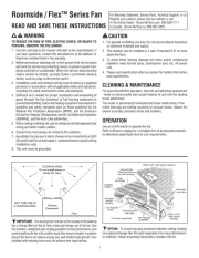
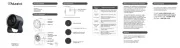
Models 744 / 744NT Recessed Fan / Light
READ AND SAVE THESE INSTRUCTIONS
WARNING
TO REDUCE THE RISK OF FIRE, ELECTRIC SHOCK, OR INJURY TO
PERSONS, OBSERVE THE FOLLOWING:
1. Use this unit only in the manner intended by the manufacturer. If
you have questions, contact the manufacturer at the address or
telephone number listed in the warranty.
2. Before servicing or cleaning unit, switch power off at service panel
and lock the service disconnecting means to prevent power from
being switched on accidentally. When the service disconnecting
means cannot be locked, securely fasten a prominent warning
device, such as a tag, to the service panel.
3. Installation work and electrical wiring must be done by a qualifi ed
person(s) in accordance with all applicable codes and standards,
including fi re-rated construction codes and standards.
4. Suffi cient air is needed for proper combustion and exhausting of
gases through the fl ue (chimney) of fuel burning equipment to
prevent backdrafting. Follow the heating equipment manufacturer’s
guideline and safety standards such as those published by the
National Fire Protection Association (NFPA), and the American
Society for Heating, Refrigeration and Air Conditioning Engineers
(ASHRAE), and the local code authorities.
5. When cutting or drilling into wall or ceiling, do not damage
electrical wiring and other hidden utilities.
6. Ducted fans must always be vented to the outdoors.
7. If this unit is to be installed over a tub or shower, it must be
marked as appropriate for the application and be connected to a
GFCI (Ground Fault Interrupter) - protected branch circuit.
8. Never place a switch where it can be reached from a tub or shower.
9. Install this unit in a fl at ceiling only.
10. For use in non fi re rated installations only.
11. Not for use in environmental air handling spaces.
12. CAUTION - RISK OF FIRE AND PERSONAL INJURY: 75W
MAX. LAMP. Use R30, BR30, PAR30L, or PAR30LN lamps only
(75W Max.). For wet locations (tub or shower) - use PAR30L or
PAR30LN (75W Max.) lamp only. Use no other lamp types. Do
not install a lamp indentifi ed for use only in enclosed luminaries.
13. Do not install in a ceiling thermally insulated to a value greater
than R60.
14. This unit must be grounded.
CAUTION
!
1. For general ventilating use only. Do not use to exhaust hazardous
or explosive materials and vapors.
2. To avoid motor bearing damage and noisy and/or unbalanced
impellers, use the cardboard protector (provided) to keep drywall
spray, construction dust, etc. off power unit.
3. Please read specifi cation label on product for further information
and requirements.
To clean trim ring / baf e: Vacuum with a soft brush attachment or
remove trim ring / baffl e and clean with a soft cloth and mild soap
or detergent. Dry thoroughly before reinstalling.
To clean inside of housing: Remove trim ring / baffl e and vacuum
inside of housing with a soft brush attachment.
OPERATION
The fan and light can be operated using various combinations of on/
off switches and timer controls:
• Fan and light controlled with single on/off switch
• Fan and light controlled with separate on/off switches
• Fan controlled with on/off switch - light with dimmer switch
• Fan controlled with timer control
Do not use a speed control to operate the fan in this unit.
See “Connect Wiring” section for various wiring options.
CLEANING
MAINTENANCE
Motor is permanently lubricated. Do not oil or disassemble motor.
See “Service Parts” section for a list and illustrations of service parts.
Two of the most common ways to connect ductwork to the unit.
HOUSING
MOUNTING
BRACKET
CEILING
JOIST
POWER
CABLE
TRIM RING / BAFFLE
FINISHED CEILING
4" ROUND
DAMPER/DUCT
CONNECTOR
PLAN THE INSTALLATION
The unit can
be installed
anywhere
between ceiling
joists using
mounting
brackets
provided.
*
Install in a fl at
ceiling only.
Typical Installation
Ducting has a strong effect on the air fl ow, noise and energy use of
the fan. Use the shortest, straighest duct routing possible for best
performance, and avoid installing the fan with smaller ducts than
recommended. Insulation around the ducts can reduce energy loss
and inhibit mold growth. Fans installed with existing ducts may not
achieve their rated airfl ow. The unit will operate most quietly and
effi ciently when located where the shortest possible duct run and
minimum number of elbows will be needed.
Plan to supply the unit with proper line voltage and appropriate power cable.
ROOF CAP **
4-IN. ROUND
ELBOW
**
4-IN. ROUND
DUCT **
WALL
CAP
**
** Purchase separately
INSTALLATION
2. Mark mounting location.
Position unit between joists and extend mounting brackets.
IMPORTANT: Position brackets so there will be an 1/8” gap
between bottom of housing and ceiling material. Mark the top of
keyhole slot on all four mounting brackets.
COOKING AREA
Do not install above
or inside this area
Cooking
Equipment
Floor
45
45
The unit must not
be installed above or
inside the cooking
area shown.
Do not install in a cooking area.
*
1/8" GAP
1. Install mounting brackets.
Slide the adjustable mounting brackets into the bracket channels
on the housing.
Bend the tabs on the cardboard protector and insert protector into
opening in housing.
NOTE: The cardboard protector shields the inside of the housing
from drywall spray and construction dust. Do not remove it until
after construction is completed.
CARDBOARD PROTECTOR
Register this product at www.broan-nutone.com/register. For Warranty
Statement, or to order Service Parts: go to www.broan-nutone.com
and type the Model in the “Model Search” fi eld at the top of the page.
Broan-NuTone LLC, 926 West State Street, Hartford, Wisconsin, USA
53027 800-558-1711
3. Pound in nails.
Remove unit temporarily, and pound
nails partially into joists at all four
marked locations.
4. Hang and secure housing.
Hang unit from nails. Check to make
sure that there will be a 1/8” gap
between bottom of housing and
ceiling material. Pound nails tight.
For wide joist centers: A #8 x 3/8
self-tapping screw can be used to
join extended brackets together and
create a rigid mount. To ensure a
noise-free mount, crimp the bracket
channels tightly around mounting
brackets.
5. Attach damper/duct connector.
Snap the damper/duct connector onto housing. Make sure that
tabs on the connector lock in housing slots. (Top of damper/duct
connector will be fl ush with top of housing.) Install ductwork.
FLUSH
NOTE: Make sure damper fl ap is in
place inside of duct connector. If it
is not: Squeeze top and bottom of
connector to snap fl ap back into
place.
Fan operated with separate on/off switch or timer.
Light operated with separate on/off switch
or dimmer switch.
7. Connect wiring.
Unit can be wired from outside of housing as shown. Use UL approved
connectors to wire per local codes.
Fan and Light operated with single on/off switch
WIRING PLATE
WHITE
TO
WHITE
BLUE (FAN)
TO
BLACK
TOP / BACK
OF HOUSING
3-WIRE PLUS
GROUND
POWER
CABLE
GROUND TO
WIRING PLATE
RED (LAMP) TO RED
WIRING PLATE
WHITE
TO
WHITE
BLUE AND RED
TO BLACK
TOP / BACK
OF HOUSING
2-WIRE PLUS
GROUND
POWER
CABLE
GROUND TO
WIRING PLATE
6. Choose power cable direction.
Remove wiring plate. When re-attached, the wiring plate allows the
power cable to enter unit horizontally or vertically.
HORIZONTAL POWER
CABLE CONNECTION
VERTICAL
POWER CABLE
CONNECTION
1102397B
9. Attach trim ring / baf e to housing.
Remove the cardboard protector from inside the housing collar.
Insert one end of each spring into the holes on the lamp bracket.
Center trim ring / baffl e in ceiling opening.
10. Install bulb.
CAUTION - RISK OF
FIRE: 75W MAX. LAMP
Use R30, BR30,
PAR30L, or PAR30LN lamps
only (75W Max.).
For wet locations (tub or
shower) - use PAR30L or
PAR30LN (75W Max.) lamp
only. Use no other lamp types.
Do not install a lamp indentifi ed
for use only in enclosed
luminaries.
FINISHED
CEILING
MATERIAL
HOUSING
COLLAR
CLEARANCE
HOLE
SPRINGS
TRIM RING /
BAFFLE
LAMP
BRACKET
8. Finish ceiling.
Cut an opening in fi nished ceiling material for housing collar.

Modelos 744 / 744NT Ventilador con lámpara empotrado
LEA Y CONSERVE ESTAS INSTRUCCIONES
ADVERTENCIA
PARA REDUCIR EL RIESGO DE INCENDIOS, DESCARGAS ELÉCTRICAS O
LESIONES PERSONALES, OBSERVE LAS SIGUIENTES PRECAUCIONES:
1. Use la unidad sólo de la manera indicada por el fabricante. Si tiene preguntas,
comuníquese con el fabricante en la dirección o el número telefónico que
se incluye en la garantía.
2. Antes de dar servicio a la unidad o de limpiarla, interrumpa el suministro
eléctrico en el panel de servicio y bloquee los medios de desconexión del
servicio para evitar que la electricidad se reanude accidentalmente. Cuando no
sea posible bloquear los medios de desconexión del servicio, fi je una señal
de advertencia (tal como una etiqueta) en un lugar visible del panel de servicio.
3. El trabajo de instalación y el cableado eléctrico deben estar a cargo
de un personal capacitado, y cumplir con todos los códigos y normas
correspondientes, incluidos los códigos y normas de construcción
específi cos sobre protección contra incendios.
4. Se necesita sufi ciente aire para que se lleve a cabo una combustión y
descarga adecuadas de los gases a través del tubo de humos (chimenea)
del equipo quemador de combustible, a fi n de evitar los contratiros. Siga las
directrices y las normas de seguridad del fabricante del equipo de calefacción,
como las publicadas por la Asociación Nacional de Protección contra Incendios
(National Fire Protection Association, NFPA), la Sociedad Americana
de Ingenieros de Calefacción, Refrigeración y Aire Acondicionado
(American Society for Heating, Refrigeration and Air Conditioning
Engineers, ASHRAE) y las autoridades de los códigos locales.
5. Al cortar o perforar a través de la pared o del cielo raso, no dañe el cableado
eléctrico ni otros servicios ocultos.
6. Los ventiladores con conductos siempre deben conectarse hacia el exterior.
7. Si se va a instalar esta unidad sobre una tina o ducha, debe estar marcada
como apropiada para esta aplicación y conectarse a un GFCI (interruptor
accionado por pérdida de conexión a tierra) en un circuito de derivación
protegido.
8. Nunca coloque el interruptor en un lugar en donde se pueda alcanzar desde
la tina o ducha.
9. Instale esta unidad en un techo plano solamente.
10. Para el uso en no fuego clasifi có instalaciones solamente.
11. No para el uso en el aire ambiental que maneja espacios.
12. PRECAUCIÓN - RIESGO DE INCENDIO Y LESIONES PERSONALES:
LÁMPARA MÁXIMO DE 75 VATIOS. Use únicamente lámparas R30,
BR30, PAR30L, o PAR30LN (máximo de 75 vatios). Para sitios expuestos
a agua (tinas o duchas): use únicamente la lámpara PAR30L o PAR30LN
(máximo de 75 vatios). No instale No utilice ningún otro tipo de lámpara.
una lámpara identifi cado para el uso solamente en lumbreras incluidas.
13. No instale en un techo aislado termalmente a un valor mayor que R60.
14. Esta unidad debe estar conectada a tierra.
PRECAUCIÓN
!
1. Sólo para usarse como medio de ventilación general. No se use para
descargar materiales ni vapores peligrosos o explosivos.
2. Para evitar daños a los cojinetes del motor y rotores ruidosos y/o no
equilibrados, utilice el protector de cartón (proporcionado) mantenga la
unidad de potencia al resguardo de polvos de yeso, de construcción, etc.
3. Lea la etiqueta de especificaciones que tiene el producto para ver
información y requisitos adicionales.
Registre este producto en www.broan-nutone.com/register. Para Declaración
de garantía, o para pedir piezas de servicio: vaya a www.broan-nutone.com y
escriba el modelo en el campo “Model Search” en la parte superior de la página.
Broan-NuTone LLC, 926 West State Street, Hartford, Wisconsin, USA 53027
800-558-1711
OPERACIÓN
El ventilador y la lámpara pueden funcionar con varias combinaciones de
interruptores de encendido/apagado y controles de regulador eléctrico:
• Ventilador y lámpara controlados con un solo interruptor de encendido/
apagado
• Ventilador y lámpara controlados con interruptores de encendido/apagado
separados
• Ventilador controlado con un interruptor de encendido/apagado; lámpara
controlada con un reductor de intensidad de la luz
• Ventilador controlado con un control de regulador eléctrico
No utilise un control de velocidad para funcionar el ventilador en esta unidad.
Vea la sección “Conecte los cables” se describen varias opciones de cableado.
LIMPIEZA
Para limpiar el anillo/defl ector: Límpielo con una aspiradora que tenga un
cepillo suave como accesorio. También puede sacar el anillo/defl ector y
limpiarlo con un trapo suave y detergente o jabón suave. Séquelo muy bien
antes de volver a instalarlo.
Para limpiar el interior de la cubierta: Saque el anillo/defl ector y aspire el interior
de la cubierta con una aspiradora que tenga un cepillo suave como accesorio.
MANTENIMIENTO
El motor está permanentemente lubricado. No lubrique ni desmonte el motor.
Vea la sección “Piezas de repuesto” se encuentra una lista con ilustraciones
de tales piezas.
Dos de las maneras más comunes de conectar conductos a la unidad.
PLANIFICACIÓN DE LA INSTALACIÓN
Esta unidad se
puede instalar en
cualquier lugar
entre las vigas del
cielo raso usando
los soportes de
montaje que se
proporcionan.
* Instale en un
techo plano
solamente.
TAPA DE TECHO **
CONDUCTO
REDONDO
DE 4 pulg.
**
CODO REDONDO
DE 4 pulg.
**
TAPA
DE
PARED
**
Se compran **
por separado
CUBIERTA
SOPORTE DE
MONTAJE
VIGA DEL
CIELO RASO
CABLE
ELÉCTRICO
ANILLO/DEFLECTOR
CIELO RASO ACABADO
*
CONECTOR DEL REGULADOR
DE TIRO/CONDUCTO
REDONDO DE 4 pulg.
INSTALACIÓN
2. Marque el sitio de montaje.
Coloque la unidad entre las vigas y extienda los soportes de montaje.
IMPORTANTE: Los soportes de la posición tan allí serán un 3,2 mm (1/8
po) abra entre el fondo de la cubierta y el material del techo. Marque la
parte superior de la ranura tipo bocallave en los cuatro soportes de montaje.
ÁREA DE COCINA
No instale el equipo
sobre o dentro de esta
área.
Equipo de
cocina
Piso
45
45
No se debe instalar la
unidad sobre el área
de cocina mostrada ni
dentro de ella.
No instale el equipo en un área de cocina.
BOQUETE DE
3,2 mm (1/8 pulg.)
1. Instale los soportes de montaje.
Inserte los soportes de montaje ajustables en los canales del soporte de
la cubierta.
Doble las lenguetas en el protector de cartón y inserte el protector en abrirse
en la cubierta.
NOTA: El protector de cartón protege el interior de la cubierta contra el
rocío de yeso y el polvo de la construcción. No lo quite sino hasta que la
construcción esté completa.
PROTECTOR DE CARTÓN
3. Martille los clavos.
Quite temporalmente la unidad y clave
parcialmente los clavos en las vigas en
los cuatro lugares marcados.
4. Cuelgue la unidad y asegúrela.
Cuelgue la unidad en los clavos.
Compruebe para cerciorarse de que
haya un 3,2 mm (1/8 po) abra entre el
fondo de la cubierta y el material del
techo. Clave los clavos fi rmemente.
Para centros de vigas anchas: Se
puede usar un tornillo autorroscante
#8 x 3/8 para unir entre sí los soportes
extendidos y crear un montaje rígido.
Para lograr un montaje silencioso, doble
los canales del soporte ajustadamente
alrededor de los soportes de montaje.
5. Acople el conectador del regulador de tiro/conducto.
Conecte a presión el conector del regulador de tiro/conducto en la cubierta.
Asegúrese de que las lengüetas del conector queden fi jas en las ranuras de
la cubierta. (La parte superior del conector del regulador de tiro/conducto
quedará al ras con la parte superior de la cubierta.) Instale los conductos.
AL RAS
NOTA: Asegúrese de que la tapa del
regulador de tiro esté colocada dentro
del conector del conducto. Si no lo
está:
Comprima la parte superior e
inferior del conector para
volver a
colocar la tapa en su lugar.
CONEXIÓN DEL CABLE
ELÉCTRICO HORIZONTAL
CONEXIÓN DEL
CABLE ELÉCTRICO
VERTICAL
Ventilador controlado mediante un interruptor de encendido/apagado o
regulador eléctrico - Lámpara controlada mediante un interruptor de
encendido/apagado o reductor de intensidad separado.
6. Elija la dirección del cable eléctrico.
Quite la placa de cableado. Una vez reinstalada, la placa de cableado permite
al cable eléctrico entrar a la unidad en sentido horizontal o vertical.
7. Conecte los cables.
El cableado de la unidad puede hacerse desde afuera de la cubierta, tal
como se muestra. Realice el cableado con conectores aprobados por UL y
en cumplimiento de los códigos locales.
Ventilador y lámpara controlados mediante un interruptor único de
encendido/apagado
PLACA DE CABLEADO
BLANCO
CON
BLANCO
AZUL
(VENTILADOR)
CON NEGRO
PARTE SUPERIOR/
PARTE POSTERIOR
DE LA CUBIERTA
CABLE
ELÉCTRICO DE
TRES HILOS Y
CONEXIÓN A
TIERRA
TIERRA A PLACA
DE CABLEADO
ROJO (LÁMPARA)
CON ROJO
PLACA DE CABLEADO
BLANCO a
BLANCO
AZUL Y ROJO a
NEGRO
PARTE
SUPERIOR/
PARTE
POSTERIOR DE
LA CUBIERTA
CABLE
ELÉCTRICO DE
DOS HILOS Y
CONEXIÓN A
TIERRA
TIERRA A PLACA
DE CABLEADO
9. Acople el anillo/de ector a la cubierta.
Quite el protector de cartón del interior del collar de la cubierta.
Inserte un extremo de cada resorte en los agujeros que están en el soporte
de la lámpara. Centre el anillo/defl ector en la abertura del cielo raso.
10. Instale la bombilla.
PRECAUCIÓN - RIESGO
DE INCENDIO: LÁMPARA
MÁXIMO DE 75 VATIOS
Use únicamente lámparas R30,
BR30, PAR30L, o PAR30LN
(máximo de 75 vatios). Para sitios
expuestos a agua (tinas o duchas):
use únicamente la lámpara
PAR30L o PAR30LN (máximo de
75 vatios). No utilice ningún otro
tipo de lámpara. No instale una
lámpara identifi cado para el uso
solamente en lumbreras incluidas.
MATERIAL
ACABADO DEL
TECHO
COLLAR DE LA
CUBIERTA
AGUJERO
DE SEPARACIÓN
RESORTES
ANILLO /
DEFLECTOR
SOPORTE
DE LÁMPARA
8. Termine el cielo raso.
Corte un orifi cio en el cielo raso terminado para la brida de la cubierta.
Los conductos tienen un gran efecto sobre el fl ujo de aire, el ruido y el uso
de energía del ventilador. Utilice el tramo de conductos más corto y recto
posible para obtener un desempeño óptimo y evite instalar el ventilador
con conductos menores que los recomendados. El aislamiento alrededor
de los conductos puede reducir la pérdida de energía e inhibir el desarrollo
de moho. Los ventiladores instalados en conductos existentes podrían no
obtener el fl ujo de aire nominal. El ventilador funcionará con más efi cacia y
menos ruido si se ubica en un sitio donde requiera el tramo de conductos
más corto posible y un mínimo número de codos.
Alimente la unidad con el voltaje de línea y el cable eléctrico apropiados.
Instalación típica
Product specificaties
| Merk: | NuTone |
| Categorie: | Ventilator |
| Model: | 744NT |
Heb je hulp nodig?
Als je hulp nodig hebt met NuTone 744NT stel dan hieronder een vraag en andere gebruikers zullen je antwoorden
Handleiding Ventilator NuTone
17 April 2025
16 April 2025
16 April 2025
16 April 2025

16 April 2025
16 April 2025

16 April 2025

16 April 2025

16 April 2025

16 April 2025
Handleiding Ventilator
- Argo
- Ufesa
- Helios
- Duronic
- Ozito
- Enermax
- Zehnder
- Optimea
- Falmec
- EXCELLENT Electrics
- Day
- Termozeta
- Tristar
- Migros
- Eligent
Nieuwste handleidingen voor Ventilator
16 September 2025
15 September 2025
15 September 2025
15 September 2025
15 September 2025
15 September 2025
15 September 2025
15 September 2025
13 September 2025
12 September 2025