Netgear RPS4000v2 Handleiding
Netgear Niet gecategoriseerd RPS4000v2
Bekijk gratis de handleiding van Netgear RPS4000v2 (2 pagina’s), behorend tot de categorie Niet gecategoriseerd. Deze gids werd als nuttig beoordeeld door 258 mensen en kreeg gemiddeld 4.4 sterren uit 9 reviews. Heb je een vraag over Netgear RPS4000v2 of wil je andere gebruikers van dit product iets vragen? Stel een vraag
Pagina 1/2
Installation Guide
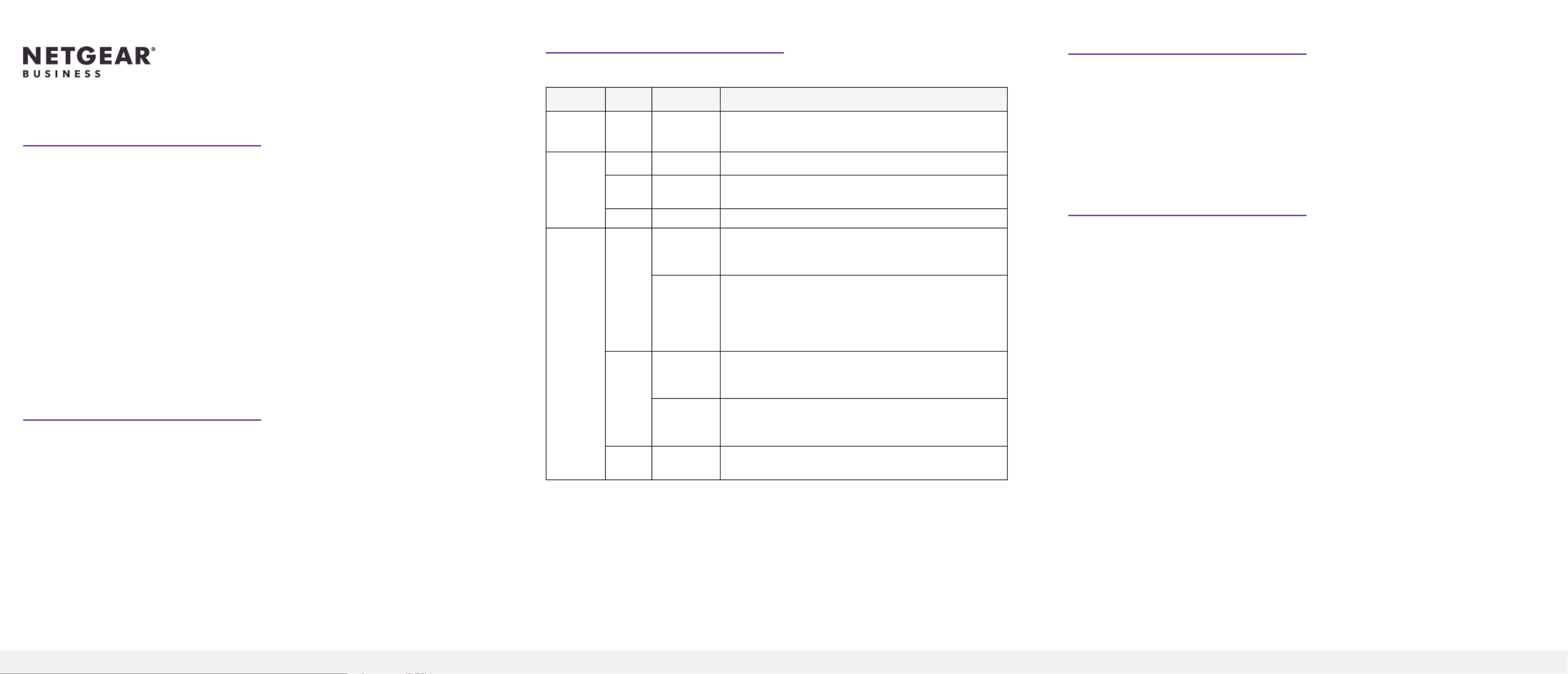
Check the LEDs
Power system indicators are listed in the following table:
LabelColor ActivityDescription
PWR
(Power)
GreenOnPower is being provided to the RPS4000v2.
Power
Module
Status
GreenOnAn APS1000W is present and working properly.
YellowOnAn APS1000W is present but is not working
properly.
OffOffThere is no APS1000W present.
RPS Port
Status
GreenOnThe switch supports dynamic power allocation, and
the APS1000W in the corresponding RPS port and
power module bay is supplying power to the switch.
BlinkingThe switch supports dynamic power allocation, but
the APS1000W in the corresponding RPS port and
power module bay is not supplying power to the
switch. Power is being supplied by the APS1000W in
a different power module bay.
YellowOnThe switch does not support dynamic power
allocation, and the APS1000W is providing power to
the switch.
BlinkingThe switch does not support dynamic power
allocation, but the APS1000W is not supplying
power to the switch.
OffOffNo power is being supplied to the switch, or the
switch is not recognized.
Redundant Power System and Power Bank
Model RPS4000v2
The Redundant Power System and Power Bank RPS4000v2 provides power
system redundancy to external devices such as NETGEAR chassis switches,
managed switches, or smart switches with an RPS capability.
Each RPS4000v2 includes four power module bays, and can provide a maximum
output of 4000W when four APS1000W power supply units (PSU) are installed.
The RPS4000v2 can supply power to devices that support dynamic power
allocation as well as to legacy devices. The RPS4000v2 acts as a redundant power
system in 12 VDC context and acts as a power bank in PoE (56 VDC) context.
Package Contents
This package includes:
• Redundant Power System and Power Bank RPS4000v2
• AC power cable
• RPS cable, 60 cm (23.6 in.),16 pin
RPS ports
Each RPS port on the RPS4000v2 can provide a maximum of 1440W at 56 VDC
and 200W at 11 VDC. Output power depends on the number of power supply
units (PSU) installed, and the settings of the Type selector and Current Share (CS)
selector on the back panel of the RPS4000v2.
To determine the RPS type for other switches, see the hardware installation guide
,which you can download by visiting netgear.com/support/download/.
Install the RPS4000v2
Install the RPS4000v2 in a standard 19-inch rack.
WARNING: Do not stack equipment, or place equipment in tight spaces or in
drawers. Be sure that your equipment is surrounded by at least 2 inches (5 cm) of
air space.
Insert a power supply unit
In models with more than one PSU, the PSUs are hot-pluggable.
1. If your switch functions with a single PSU only, disconnect the power cord
from the PSU and let the switch power down.
If your switch functions with more than one PSU, you do not need to power
down the switch and you can perform a hot swap.
2. Remove the PSU from the power module bay by moving the orange release
latch to the left and pulling the extraction handle.
3. Insert the replacement PSU into the power module bay, and gently push the
PSU into the bay until the latch locks.
CAUTION: When inserting the PSU, do not use unnecessary force. Doing so
can damage the connectors on the back of the PSU and on the midplane.
4. Connect the end of the power cord to the power receptacle on the PSU.
Product specificaties
| Merk: | Netgear |
| Categorie: | Niet gecategoriseerd |
| Model: | RPS4000v2 |
| Kleur van het product: | Grijs |
| LED-indicatoren: | Ja |
| Rack-montage: | Ja |
| Compatibiliteit: | Netgear M6100-3S |
| Code geharmoniseerd systeem (HS): | 85177900 |
Heb je hulp nodig?
Als je hulp nodig hebt met Netgear RPS4000v2 stel dan hieronder een vraag en andere gebruikers zullen je antwoorden
Handleiding Niet gecategoriseerd Netgear

22 April 2026
30 Maart 2026
17 Maart 2026
29 September 2025
29 September 2025
29 September 2025
29 September 2025
28 Juli 2025
4 Juli 2025
15 Juni 2025
Handleiding Niet gecategoriseerd
Nieuwste handleidingen voor Niet gecategoriseerd
8 Juni 2026
8 Juni 2026
8 Juni 2026
8 Juni 2026
8 Juni 2026
8 Juni 2026
8 Juni 2026
8 Juni 2026
8 Juni 2026
8 Juni 2026