Moxa NPort IA-5250I Handleiding
Bekijk gratis de handleiding van Moxa NPort IA-5250I (4 pagina’s), behorend tot de categorie Server. Deze gids werd als nuttig beoordeeld door 20 mensen en kreeg gemiddeld 4.6 sterren uit 10.5 reviews. Heb je een vraag over Moxa NPort IA-5250I of wil je andere gebruikers van dit product iets vragen? Stel een vraag
Pagina 1/4
— 1 — — 2 — — 3 —
NPort IA5250I/5250I-T Series
Quick Installation Guide
First Edition, October 2009
1. Overview
NPort IA device servers deliver easy and reliable serial-to-Ethernet
connectivity for the industrial automation market. The servers support
several operation modes—TCP Server, TCP Client, UDP, Real COM,
Pair Connection, and Ethernet Modem—ensuring the compatibility of
network software, and are an ideal choice for connecting
RS-232/422/485 serial devices, such as PLCs, sensors, meters, motors,
drives, barcode readers, and operator displays. NPort IA5250I/5250I-T
device servers come with a compact and rugged DIN-Rail mountable
casing.
2. Package Checklist
Before installing NPort IA device servers, verify that the package
contains the following items:
• 1 NPort IA Series Device Server
• Documentation and Software CD
• NPort IA Series Quick Installation Guide
Optional Accessories
y DR-4524 45W/2A DIN-Rail 24 VDC Power Supply with
universal 85 to 264 VAC input
y DR-75-24 75W/3.2A DIN-Rail 24 VDC Power Supply with
universal 85 to 264 VAC input
y DR-120-24 120W/5A DIN-Rail 24 VDC Power Supply with 88
to 132 VAC/176 to 264 VAC input by switch
Notify your sales representative if any of the above items is missing or
damaged.
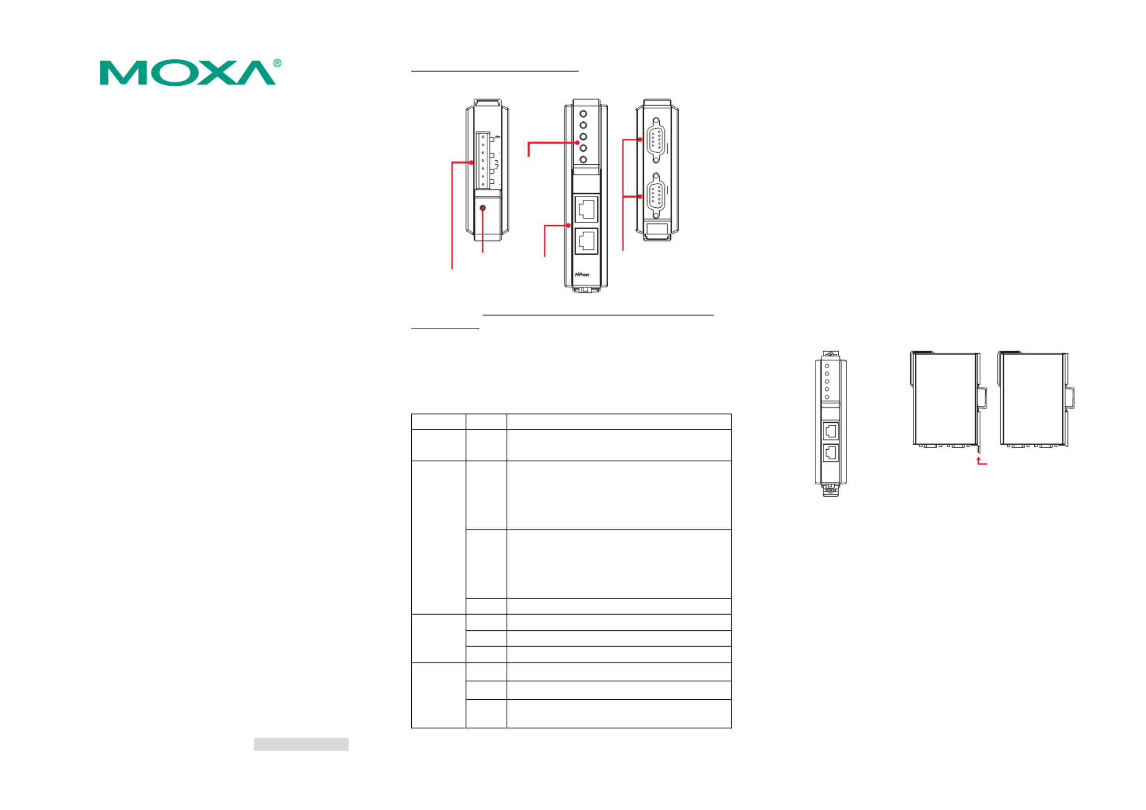
3. Hardware Introduction
NPort IA5250I/5250I-T device servers are used to control
RS-232/422/485 devices for industrial automation environments. NPort
5250I/5250I-T has 2 RS-232/422/485 male DB9 serial ports with 2KV
isolation for all interfaces.
NPort IA5250I/5250I-T Appearance
PWR1
PWR2
RDY
P1
Ethernet 1
Ethernet 2
Reset
5250
IA
P2
Copper
Ethernet
LED
Indicators
Top View Bottom ViewFront View
Reset
V1
V1+
V2
V2+
1
Dual power input
and relay output
RS-232/422/485
RS-232/422/485P1 P2
I
Reset Button—Press the Reset button continuously for 5 sec to load
factory defaults: Use a pointed object, such as a straightened paper clip or
toothpick, to press the reset button. This will cause the Ready LED to
blink on and off. The factory defaults will be loaded once the Ready LED
stops blinking (after about 5 seconds). At this point, you should release
the reset button.
NPort IA LED Indicators (front panel)
Name Color Function
PWR1,
PWR2 red Power is being supplied to power input PWR1,
PWR2.
red
Steady on: Power is on and NPort IA is booting
up.
Blinking: Indicates an IP conflict, the DHCP
or BOOTP server did not respond
properly, or a relay output occurred.
green
Steady on: Power is on and NPort IA is
functioning normally.
Blinking: The device server has been located
by Administrator’s Location
function.
Ready
off Power is off, or a power error condition exists.
Orange 10 Mbps Ethernet connection.
Green 100 Mbps Ethernet connection.
Ethernet
off Ethernet cable is disconnected, or has a short.
orange Serial port is receiving data.
green Serial port is transmitting data.
P1, P2
off No data is being transmitted or received through
the serial port.
4. Hardware Installation Procedure
STEP 1: After removing NPort IA from the box, the first thing you
should do is connect the power adaptor. Connect the 12-48
VDC power line with NPort IA’s terminal block, or connect
the DIN-Rail power supply with NPort IA’s terminal block.
STEP 2: Connect NPort IA to a network. Use a standard
straight-through Ethernet cable to connect to a Hub or
Switch. When setting up or testing NPort IA, you might find
it convenient to connect directly to your computer’s Ethernet
port. In this case, use a cross-over Ethernet cable.
STEP 3: Connect NPort IA’s serial port to a serial device.
STEP 4: NPort IA is designed to be attached to a DIN-Rail or
mounted on a wall. The two sliders on NPort IA’s rear panel
serve a dual purpose. For wall mounting, both sliders should
be extended. For DIN-Rail mounting, start with one slider
pushed in, and the other slider extended. After placing the
NPort IA on the DIN-Rail, push the extended slider in to
lock the device server to the rail. The two placement options
are illustrated in the accompanying figures.
Wall Mount DIN-Rail
Push here to lock
to the DIN-Rail
5. Software Installation Information
To install NPort Administration Suite, insert the Document &
Software CD into your computer’s CD-ROM drive. Once the
installation window opens, click on the Installation Administration
Suite button, and then follow the instructions on the screen. To view
detailed information about NPort IA Administration Suite, click on
the Documents button, and then select NPort IA5250I/5250I-T Series
User’s Manual to open the pdf version of this user’s manual.
P/N: 1802051500212


— 4 — — 5 — — 6 —
6. Pin Assignments and Cable Wiring
RS-232/422/485 (Male DB9) Pinouts
12345
6789
PIN RS-232 RS-422/
RS-485 (4W) RS-485 (2W)
1 DCD TxD-(A) ---
2 RXD TxD+(B) ---
3 TXD RxD+(B) Data+(B)
4 DTR RxD-(A) Data-(A)
5 GND GND GND
6 DSR --- ---
7 RTS --- ---
8 CTS --- ---
9 --- --- ---
Four cables are available as optional accessories that can be used to
connect NPort IA to RS-232 serial devices. For your convenience, we
show precise cable wiring diagrams for each of the two cables.
Female DB9 to Male DB9
NPort IA
9 pins 9 pins
DCD
RxD
TxD
DTR
GND
DSR
RTS
CTS
RS-232
Device
DCD
TxD
RxD
DSR
GND
DTR
CTS
RTS
Cable Wiring
1
2
3
4
5
6
7
8
1
2
3
4
5
6
7
8
Female DB9 Male DB9Male DB9 Female DB9
Female DB9 to Male DB25
NPort IA
9 pins 25 pins
DCD
RxD
TxD
DTR
GND
DSR
RTS
CTS
RS-232
Device
DCD
TxD
RxD
DSR
GND
DTR
CTS
RTS
Cable Wiring
1
2
3
4
5
6
7
8
8
3
2
20
7
6
4
5
Female DB9 Male DB25Male DB9 Female DB25
7. Specifications
Power requirements NPort IA5250I/5250I-T: 12 to 48 VDC, 440 mA
at 12 V (max.)
Operating temp. 0 to 55°C (32 to 131°F),
-40 to 75◦C (-40 to 167◦C) for wide temp model
Operating humidity 5 to 95% RH
Dimensions
(W×D×H)
29 × 89.2 × 118.5 mm
1.14 × 3.51 × 4.67 in
Surge protection 15 KV ESD for all signals
Isolation protection 2KV for RS-232/422/485
Magnetic isolation 1.5 KV for Ethernet
Power line protection 4 KV Burst (EFT), EN61000-4-4
2 KV Surge, EN61000-4-5
Regulatory approvals FCC Class A, CE Class A
Click here for online support:
www.moxa.com/support
The Americas: +1-714-528-6777 (toll-free: 1-888-669-2872)
Europe: +49-89-3 70 03 99-0
Asia-Pacific: +886-2-8919-1230
China: +86-21-5258-9955 (toll-free: 800-820-5036)
©
©
©
©© 2009 Moxa Inc. All rights reserved.
Reproduction without permission is prohibited.
Product specificaties
| Merk: | Moxa |
| Categorie: | Server |
| Model: | NPort IA-5250I |
| Gewicht: | 380 g |
| LED-indicatoren: | Ja |
| Soort serieële aansluiting: | RS-232/422/485 |
| Certificering: | CE, FCC |
| Temperatuur bij opslag: | -40 - 85 °C |
| Compatibele besturingssystemen: | Windows 95, 98, ME, NT, 2000, XP, 2003, Vista, XP x64, 2003 x64, Vista x64\r\nSCO Unix, SCO OpenServer, UnixWare 7, UnixWare 2.1, SVR 4.2, QNX 4.25, QNX 6, Solaris 10, FreeBSD, AIX 5.x, HP-UX 11i\r\nLinux kernel 2.4.x, 2.6.x |
| Ondersteunde netwerkprotocollen: | ICMP, IP, TCP, UDP, DHCP, BOOTP, Telnet, Rtelnet, DNS, SNMP V1, HTTP, SNTP |
| Veiligheid: | UL (UL60950-1), UL508, TÜV (EN60950-1) |
| Afmetingen (B x D x H): | 29 x 89.2 x 118.5 mm |
| Link/Act LED: | Ja |
| Seriële poort(en): | 2 |
| Beheerprotocollen: | SNMP v1 |
| Bedrijfstemperatuur (T-T): | 0 - 55 °C |
| Relatieve vochtigheid in bedrijf (V-V): | 5 - 95 procent |
| Isolatie: | 2 kV |
Heb je hulp nodig?
Als je hulp nodig hebt met Moxa NPort IA-5250I stel dan hieronder een vraag en andere gebruikers zullen je antwoorden
Handleiding Server Moxa

2 Augustus 2023

2 Augustus 2023

2 Augustus 2023

2 Augustus 2023

2 Augustus 2023

2 Augustus 2023

2 Augustus 2023

2 Augustus 2023

2 Augustus 2023

2 Augustus 2023
Handleiding Server
- Iomega
- Trendnet
- Elac
- EMC
- Linksys
- Asustor
- Provision ISR
- AMX
- Medion
- Technics
- Promise Technology
- OWC
- C2G
- Axis
- Middle Atlantic
Nieuwste handleidingen voor Server

30 Juli 2025
30 Juli 2025
29 Juli 2025
29 Juli 2025
29 Juli 2025
29 Juli 2025
29 Juli 2025
29 Juli 2025

29 Juli 2025

29 Juli 2025