Microsemi PD-3501G/AC Handleiding
Microsemi
Netwerkkaart/adapter
PD-3501G/AC
Bekijk gratis de handleiding van Microsemi PD-3501G/AC (4 pagina’s), behorend tot de categorie Netwerkkaart/adapter. Deze gids werd als nuttig beoordeeld door 30 mensen en kreeg gemiddeld 4.3 sterren uit 15.5 reviews. Heb je een vraag over Microsemi PD-3501G/AC of wil je andere gebruikers van dit product iets vragen? Stel een vraag
Pagina 1/4

MMiiccrroosseemmii 33550011GG UUsseerr GGuuiiddee
1
1-
-P
Po
or
rt
t
8
80
02
2.
.3
3a
af
f
G
Gi
ig
ga
ab
bi
it
t
P
Po
oE
E
M
Mi
id
ds
sp
pa
an
n
Notice
It is Microsemi’s policy to improve its products as new
technology, components, software, and firmware become
available. Microsemi, therefore, reserves the right to change
specifications without prior notice.
Technical Support
If you encounter problems when installing or using this
product, please consult the Microsemi website at:
http://www.Microsemi.com
For technical support, call: +972-9- - 775 5123
In the USA: 1-877- -2323 480
Email: sales.support@microsemi.com
Microsemi Corp.
Recycling and Disposal
Disposal instructions for old products. The WEEE
(Waste Electrical and Electronic Equipment)
national environmental initiatives has been put
in place to ensure that products are recycled
using best available treatment, recovery and
and recycling techniques to ensure human
health and high environmental protection. Your
product is designed and manufactured with
high quality materials and components which
can be recycled and reused. Do not dispose of
your old product in your general household
waste bin. Inform yourself about the local
separate collection system for electrical and
electronic products marked by this symbol:
Use one of the following disposal options :
1. Dispose of the complete product (including
its cables, plugs and accessories) in the
designated WEEE collection facilities.
2. If you purchase a replacement product,
return your old product (including all er
components) back to the retailer. The retailer
should accept it as required by the national
WEEE legislation.
Note: Unless otherwise noted, references to the
PD-3501G/AC in this document refer to both the PD-3501/AC
and the PD-3501G/AC.
Ordering information:
1-Port 802.3af Gigabit PoE Midspan:
o oduct Name: Microsemi Pr 3501G
o Part Number: -3501G/AC PD
1-Port 802.3af PoE Midspan
o Product Name: Microsemi 3501
o Part Number: -3501/AC PD
Document P/N: 06- -056 Rev. B00 0066
Safety Information
Important Safety Information
The -3501G should be connected to PoE networks PD
only, without routing to the outside plant.
Only qualified personnel can install or remove the
PD- . 3501G
AC Power Cord Set:
The power cord must have regulatory agency approval for
the specific country in which it is used (for example UL,
CSA, VDE, etc.).
The power cord must be a three-conductor type (two
current carrying conductors; one ground conductor)
terminated on one end by an IEC 60320 appliance coupler
(for connection to the -3501G), and on the other end by PD
a plug containing a ground (earthing) contact.
The power cord must be rated for a minimum of 250 VAC
RMS operation, with a minimum rated current capacity of
5 amps (or a minimum wire gauge of 18 AWG (0.75 mm2).
: A PD- installed in Australia requires power cords 3501G
with a minimum wire gauge of 16 AWG (1.0 mm2
).
: The - "DATA IN" and "DATA POWER OPD 3501G & UT"
ports are shielded RJ45 data sockets. They be used as cannot
Plain Old Telephone Service (POTS) telephone sockets. Only
RJ45 data connectors can be connected to these sockets.
The AC wall socket-outlet must be near the - PD 3501G
and easily accessible. You can remove AC power from
the - by disconnecting the AC power cord from PD 3501G
either the wall socket-outlet or the - appliance PD 3501G
coupler.
The -3501G DATA IN DATA POWER O PD and & UT
interfaces are qualified as Safety Extra-Low Voltage
(SELV) circuits according to IEC 60950-1. These
interfaces can only be connected to SELV interfaces on
other equipment.
WARNINGS!
The -3501G should only be connected to the IP PD
device with which it was bought. Using the -3501G PD
with other IP devices can cause damage to the IP
device.
Read the installation instructions before connecting the
PD- to its power source. 3501G
Follow basic electricity safety measures whenever
connecting the -3501G to its power source. PD
A voltage mismatch can cause equipment damage and
may pose a fire hazard. If the voltage indicated on the
label is different from the power outlet voltage, do not
connect the - to this power outlet. PD 3501G
The unit can be used only in Restricted Access
Locations.

*
Troubleshooting
Symptom
Corrective Steps
PD-3501G
does not
power up
1 Verify that a reliable power cord .
is used.
2 Verify that the voltage at the .
power inlet is between 100 and 240
VAC.
3 Remove and re-apply power to .
the device and check the indicators
during power up sequence.
The PD
does not
operate
1 Verify that the PD- 01G detects . 35
a PD.
2 Verify that the PD is designed for .
PoE operation.
3 Verify that you are using a .
standard Category 5/5e/6, straight-
wired cable, with four pairs.
4 If an external power splitter is in .
use, replace it with a known-good
splitter.
5 Ensure input Ethernet cable is .
connected to the DATA IN port.
6 Verify that the PD is connected .
to the Data & Power port.
7 Try to reconnect the same PD .
into a different -3501G. If it PD
works, there is probably a faulty port
or RJ45 connection.
8 Verify that there is no short over .
any of the twisted pair cables or
over the RJ45 connectors.
The end
device
operates,
but there
is no data
link
1 Verify that the port indicator on .
the front panel is continuously lit.
2 If an external power splitter is in .
use, replace it with a known-good
splitter.
3 Verify that for this link, you are .
using standard UTP/FTP Category 5
straight (non-crossover) cabling,
with all four pairs.
4 Verify that the Ethernet cable .
length is less than 100 meters from
the Ethernet source to the
load/remote terminal.
5 Try to reconnect the same PD .
into a different PD-3501G. If it
works, there is probably a faulty port
or RJ45 connection.
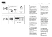
Port Connectivity
Indication
Ethernet
Cat . 5 Cable
Terminal
Figure 1: Connecting the -3501G PD
Indicators
Port LED
Indicated Behavior
Yellow On
Power is on (power is active)
Green On
A remote terminal is connected
Green Blinking
Overload state or short-circuit
Specifications
Environmental Specifications
Mode
Temperature
Humidity
Operating
0 to 40°C
32 to 104°F
10 to 90%; (no
condensation
allowed)
Storage
-20 to 70°C
-4 to 158°F
10 to 90%; (no
condensation
allowed)
Electrical Specifications
Input Voltage
100-240 VAC (50/60 Hz)
Maximal Input Current
0.43 Ampere
Guaranteed Output power
15.4 Watts
Nominal Output Voltage
48VDC
Ethernet Interface
Input (DATA IN): Ethernet
10/100/1000Base-T
RJ45 female socket
Output (DATA & POWER
OUT): Ethernet
10/100/1000Base-T, plus
48VDC
RJ45 female socket, with
DC voltage on wire pairs,
4- (+) & 7-8 (- 5 ).
Functions and Features
The -3501G Power over Ethernet (PoE) is a Single Port PD
Midspan that offers a compact and cost effective power solution
for IP phones, WLAN access points, network cameras and other
IP terminal installations.
The -3501G converts AC power to VDC power is then PD 48
provided over the Ethernet cable.
The PD-3501 supports 10/100 Mbps pass through
data rates while the PD-3501G supports up to
Mbps pass through data rates .
The single port -3501G can be powered via universal PD
AC input.
PD- 01G EMC Compliance35 :
FCC Part 15 class B and EN55022 class B
EN55024
VCCI
PD- 0 Safety Compliance: 35 1G
UL/cUL per 60950-1 2nd Ed.
GS mark
Preliminary Steps
Ensure that AC power is applied to the -3501GPD ,
using an operational AC cable with an appropriate
ground connection.
Ensure that output Ethernet cable is connected to the
DATA POWER O port. & UT
Verify that power ready Ethernet compatible device is
connected.
WARNING
Do not use cross over cable between the - output PD 3501G
port and the load device
Installation
The -3501G can be placed on a desktop. PD
: Before placing the - : PD 3501G
Do not to cover -3501G or block the airflow to the PD
PoE with any foreign objects. Keep the -3501G away PD
from excessive heat and humidity and free from
vibration and dust.
Ensure that the cable length from Ethernet network
source to the terminal does not exceed 100 meters
(330 feet). The PoE is not a repeater and does not
amplify the Ethernet data signal.
Use a splitter if desired; ensure that the splitter is
connected close to the terminal and not on the
PD- ! 3501G
- -3501G into No “on off” switch exists; simply plug the PD
an AC power source.
Installing the Unit
Refer to Figure 1.
1. Connect the -3501G to an AC outlet (100 - VAC), using PD 240
a standard power cord.
2. Connect the DATA IN jack (input) to the remote Ethernet
network switch's Patch panel and the DATA & POWER OUT jack
(output) to the terminal.
Product specificaties
| Merk: | Microsemi |
| Categorie: | Netwerkkaart/adapter |
| Model: | PD-3501G/AC |
| Gewicht: | 200 g |
| LED-indicatoren: | Ja |
| Stroom: | 0.5 A |
| Aantal Ethernet LAN (RJ-45)-poorten: | 1 |
| Certificering: | RoHS\nWEEE\nCE |
| Voldoet aan industriestandaarden: | 802.3af |
| Ingangsspanning: | 90 - 264 V |
| Ethernet LAN, data-overdrachtsnelheden: | 10,100,1000 Mbit/s |
| Bekabelingstechnologie: | 10/100/1000BaseT |
| Temperatuur bij opslag: | -20 - 70 °C |
| Frequentie: | 47 - 63 Hz |
| Luchtvochtigheid bij opslag: | 5 - 95 procent |
| Elektromagnetische compatibiliteit: | FCC Part 15, Class B EN 55022 Class B EN 55024, VCCI |
| Veiligheid: | UL/cUL per EN 60950-1, GS Mark Per IEC 60950-1 |
| Ethernet interface type: | Gigabit Ethernet |
| Hoogte, in bedrijf: | -304.8 - 3048 m |
| Afmetingen (B x D x H): | 53 x 140 x 32.5 mm |
| Bedrijfstemperatuur (T-T): | 0 - 40 °C |
| Relatieve vochtigheid in bedrijf (V-V): | 10 - 90 procent |
| Code geharmoniseerd systeem (HS): | 85044095 |
| Stroom via Ethernet (PoE): | 48 V |
Heb je hulp nodig?
Als je hulp nodig hebt met Microsemi PD-3501G/AC stel dan hieronder een vraag en andere gebruikers zullen je antwoorden
Handleiding Netwerkkaart/adapter Microsemi

18 Februari 2024

18 Februari 2024

18 Februari 2024

18 Februari 2024

18 Februari 2024
Handleiding Netwerkkaart/adapter
- Rosewill
- Eminent
- TP Link
- EXSYS
- Tenda
- ELO
- Mikrotik
- Vivanco
- Hawking Technologies
- Luminex
- Intermec
- Elecom
- Lancom
- Motu
- Approx
Nieuwste handleidingen voor Netwerkkaart/adapter
16 September 2025
15 September 2025
15 September 2025
31 Augustus 2025

11 Augustus 2025

11 Augustus 2025
5 Augustus 2025

29 Juli 2025

28 Juli 2025
28 Juli 2025