Microchip SY88952L Handleiding
Microchip Niet gecategoriseerd SY88952L
Bekijk gratis de handleiding van Microchip SY88952L (7 pagina’s), behorend tot de categorie Niet gecategoriseerd. Deze gids werd als nuttig beoordeeld door 43 mensen en kreeg gemiddeld 4.2 sterren uit 9 reviews. Heb je een vraag over Microchip SY88952L of wil je andere gebruikers van dit product iets vragen? Stel een vraag
Pagina 1/7
1
SY88952L Evaluation BoardMicrel
M9999-061704
[email protected] or (408) 955-1690
DESCRIPTION
The SY88952L features:
■Multirate up to 2.7Gbps operation
■Rise/fall times <75ps
■Independently programmable laser modulation and
bias currents
■Bias current to 100mA and modulation current to 90mA
■Automatic average laser power control
■Bias and modulation current monitors
■Complies with ANSI, ITU, and Bellcore SDH/SONET
specifications
■3.3V power supply; wide temperature operating range
The SY88952L evaluation board features:
■DC-coupled inputs and outputs with SMA connectors
■50Ω input network termination
■Potentiometers to adjust modulation and bias currents
■MD emulator to test APC functionality
FUNCTIONAL FEATURES
3.3V, 2.7Gbps SDH/SONET
LASER DRIVER WITH
AUTOMATIC POWER CONTROL
SY88952L
EVALUATION BOARD
Rev.: AAmendment: /0
Issue Date:June 2004
The SY88952L is a highly integrated and programmable
laser driver for SONET/SDH applications up to 2.7Gbps.
The device accepts differential PECL data and clock inputs.
It provides programmable bias and modulation currents for
driving a laser. The modulation output of the SY88952L can
be DC-coupled to drive the laser diode, providing significant
power savings over AC-coupled operation.
An automatic power controller (APC) is integrated into
the SY88952L to maintain a constant average optical output
power over temperature and lifetime. The moduation current
can be externally temperature compensated to minimize
the variation of the extinction ration of the optical output.
This manual provides information on the SY88952L
evaluation board. It should be used in conjunction with the
SY88952L data sheet, which contains full specifications of
the SY88952L.
The SY88952L evaluation board enables fast and
thorough evaluation of the SY88952L 2.7Gbps SDH/SONET
laser driver with automatic power control. The board is an
easy-to-use, 4-layer high-speed coplanar design that uses
Rogers 4003 dielectric material to achieve high bandwidth.
The layer stack is shown in Table 1.
The SY88952L evaluation board is designed to be driven
by a high-speed 2.7Gbps pattern generator and is intended
to be terminated to a 50Ω scope. This allows the user to
evaluate various parameters of the SY88952L, as listed in
the "Available Measurements" section of this document.
All data sheets and support documentation can be found
on Micrel’s web site at www.micrel.com.
LayerDefinition
1Signal/GND
2GND
3VEE
4GND
Table 1.SY88952L Evaluation
Board Layer Stack-Up
AVAILABLE MEASUREMENTS
The SY88952L evaluation board allows the following
measurements:
■Frequency performance
■Output eye pattern generation
■Mask testing
■Jitter
■Output rise/fall time
■BER testing
■APC functionality
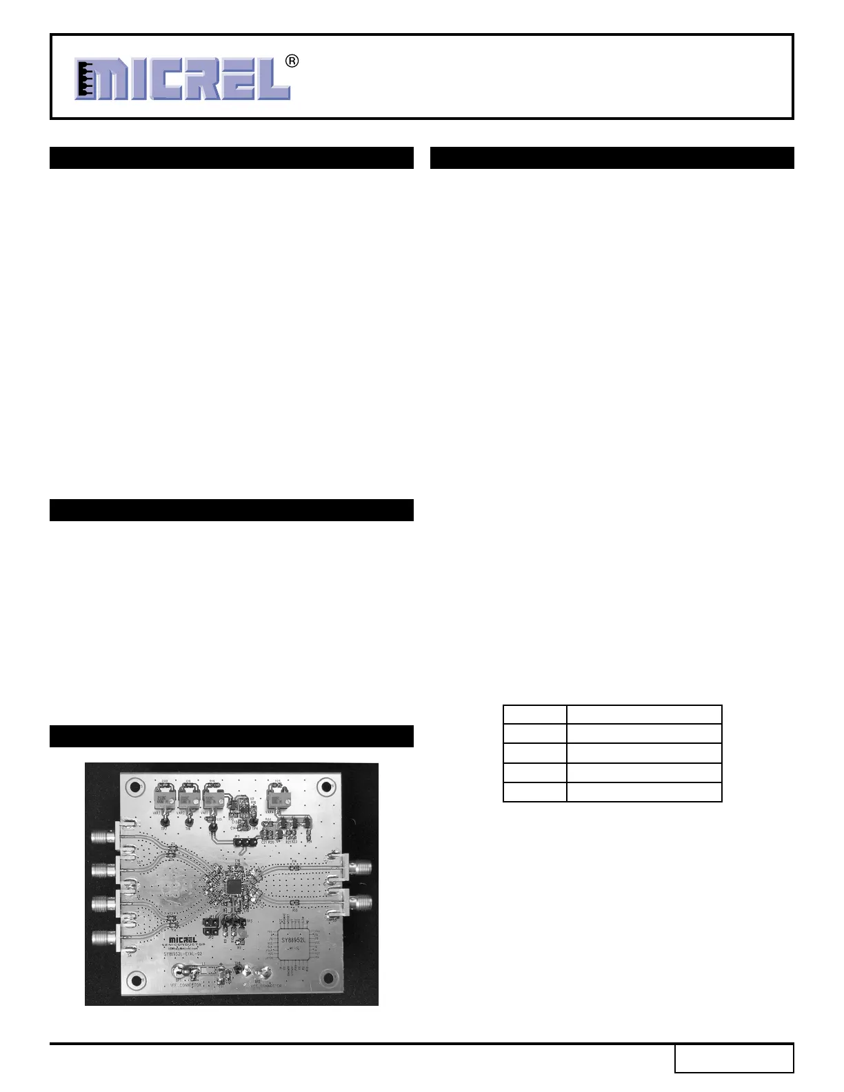
EVALUATION BOARD
Figure 1.SY88952L Evaluation Board
Product specificaties
| Merk: | Microchip |
| Categorie: | Niet gecategoriseerd |
| Model: | SY88952L |
Heb je hulp nodig?
Als je hulp nodig hebt met Microchip SY88952L stel dan hieronder een vraag en andere gebruikers zullen je antwoorden
Handleiding Niet gecategoriseerd Microchip

2 Februari 2026
26 Januari 2026
13 Januari 2026
12 Januari 2026
12 Januari 2026
12 Januari 2026
12 Januari 2026
12 Januari 2026
6 December 2025
5 December 2025
Handleiding Niet gecategoriseerd
Nieuwste handleidingen voor Niet gecategoriseerd
12 Juni 2026
12 Juni 2026
12 Juni 2026
12 Juni 2026
12 Juni 2026
11 Juni 2026
11 Juni 2026
11 Juni 2026
11 Juni 2026
11 Juni 2026