Metrix MX 531 Handleiding


Lees hieronder de 📖 handleiding in het Nederlandse voor Metrix MX 531 (6 pagina's) in de categorie Meetapparatuur. Deze handleiding was nuttig voor 14 personen en werd door 2 gebruikers gemiddeld met 4.5 sterren beoordeeld

Pagina 1/6
FR - Notice de fonctionnement
MX 531
Contrôleur de terre & testeur RCD 30 mA
V
HOLD RCD 30 mA
PE
LN NL
R
E
FR
1. GÉNÉRALITÉS
Vous venez d’acquérir un Contrôleur de terre et Testeur de
disjoncteur di󰀨érentiel RCD 30 mA et nous vous remercions
de votre conance.
Le MX 531, en régime TT uniquement, a󰀩che l’état de
raccordement de la prise électrique grâce à un a󰀩chage
LCD avec fond d’écran qui change de couleur en fonction
de la conformité de l’installation : bleu si l’installation est
conforme, rouge en cas de défaut ou de mauvaise terre.
Les prises compatibles : Les prises de type E (polarisée:
phase et neutre repérés) en France et en Belgique et les
prises de type F (non polarisée : phase et neutre non
repérés).
Si la valeur RE est correcte, < 100 Ω, le test 30 mA est
réalisable.
L’appareil connecté à une prise 2P+T sur une installation
correctement raccordée (terre présente, réseau 230 V,
phase à droite ou à gauche) a󰀩che la valeur, la tension et
mesure de l’impédance de terre RE instantanément sur la
partie inférieure de l’écran LCD 2000 points.
Pour votre sécurité et celle des biens :
- lisez attentivement cette notice de fonctionnement et
conservez là.
- respectez les précautions d’emploi.
ATTENTION, risque de DANGER ! L’opérateur
doit consulter la présente notice à chaque fois que
ce symbole de danger est rencontré.
Le marquage CE indique la conformià la Directive
européenne Basse Tension 2014/35/UE, à la
Directive Compatibilité Électromagnétique 2014/30/
UE et à la Directive sur la Limitation des Substances
Dangereuses RoHS 2011/65/UE et 2015/863/UE.
La poubelle barrée signie que, dans l’Union
Européenne, le produit fait l’objet d’une collecte
sélective conformément à la directive DEEE
2012/19/UE. Ce matériel ne doit pas être traité
comme déchet ménager.
Appareil protégé par une isolation double.
Dénition des catégories de mesure
La catégorie de mesure IV correspond aux mesurages
réalisés à la source de l’installation basse tension.
Exemple : arrivée d’énergie, compteurs et dispositifs de
protection.
La catégorie de mesure III correspond aux mesurages
réalisés dans l’installation du bâtiment.
Exemple : tableau de distribution, disjoncteurs,
 machinesouappareilsindustrielsxes.
La catégorie de mesure II correspond aux mesurages
réalisés sur les circuits directement branchés à
l’installation basse tension.
Exemple : alimentation d’appareils électrodomestiques
et d’outillage portable.
2. PRÉCAUTIONS D’EMPLOI
Ce testeur est conforme à la norme de sécurité IEC
61010-2-030 et IEC 61557-1, 3 et 6 pour des tensions
de 300 V catégorie III.
Le non-respect des précautions d’emploi peut entraîner
un risque de choc électrique, de feu, d’explosion, de
destruction de l’appareil et des installations.
Lopérateur et/ou lautorité responsable doit lire
attentivement et avoir une bonne compréhension des
di󰀨érentes précautions d’emploi. Une bonne connaissance
et une pleine conscience des risques des dangers
électriques est indispensable pour toute utilisation de cet
appareil.
La curité de tout système qui pourrait intégrer ce testeur
relève de la responsabilité de l’assembleur du système.
Avant chaque utilisation, vériez l’ingrité des ches de la prise.
ATTENTION. Ce testeur n’est pas un VAT. Utiliser
un appareil approprié pour cette opération
3. SPÉCIFICATIONS DU MX 531
Conditions d’environnement :
Utilisation à l’intérieur
Domaine d’utilisation : -10 à +45°C, 10 à 90 % HR
(jusqu’à 35°C)
Température de stockage : -20°C à 70°C
Altitude : utilisation jusqu’à 2000,
stockage jusqu’à 10 000 m.
Degré de pollution : 2
Conditions de référence :
Température : 23°C ± 3°C
Humidité relative : 45 % à 75 %HR
Champs électrique : < 0,1 V/m AC
Conditions de mesure :
Pour la mesure de tension :
Fréquence : 45 à 65 Hz
Facteur de crête : 2
Pas de composante continue, signal sinus
Pour la mesure de RE :
UL-N 230 VAC ± 0,5 %
Pas d’harmonique
UN-PE 0 V
Fréquence : 50/60 Hz ± 0,1 Hz
Test RCD si RE ≤ 100 Ω:
230 VAC ± 0,5 %
Pas d’harmonique
UL-N ± 1 V - 50/60 Hz ± 0,1 Hz
UL-PE < 1 V
IL-N 0 mA
Inuences de mesure :
Quantité d’inuence Gamme dinuence Inuence
Température -10 … + 45 °C
± (0,5 % R + 1 D) /10°C
Humidité relative 10 … 90 % HR ± (0,5 % R + 1 D)
Signal demi-alternance 330 V PEAK ± (1 % R + 1 D)
Fréquence [47,5 ; 52,5 Hz]
[57 ; 63 Hz] ± (1 % R + 1 D)
CEM : Le MX 531 est conforme à la norme IEC 61326-1.
Mesure de tension De 100 V à 400 V AC
Mesure phase neutre 0 V à 420 V
fréquence 50/60 Hz
OL si > 420 V
Résolution 1 V
Précision +/-(2 % +1 D)
Mesure de terre RE 3 Ω à 199,9 Ω 180 Ω à 1999 Ω
Résolution 0,1 Ω 1 Ω
Précision +/-(3 % L+ 5 D)
RCD 30 mA AC Si RE correct
Valeur nominale 30 mA et temps < 200 ms
Conditions 230 V phase et neutre et 0 % et +6% +/- 4 ms
Mécanique :
Dimensions : 185 x 65 x 53 mm
Masse : 230 g ± 50 g
Indice de protection : IP 4X selon IEC 60029 (MX 531 connecté)
Indice de choc : IK07 selon IEC 62262 : 2002
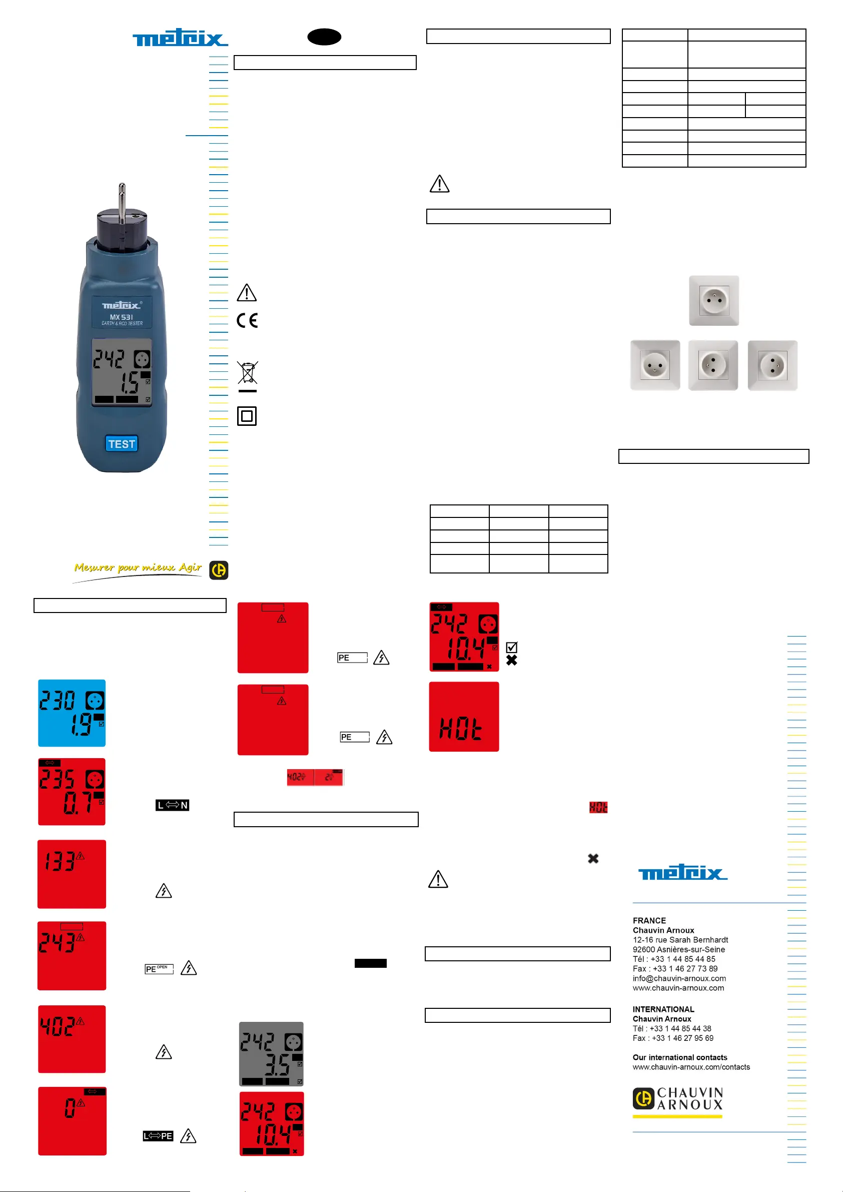
Contrôle de la prise :
La che montée sur l’instrument se connecte sur une prise
CEE 7/7. Elle est compatible avec la prise CEE 7/5 de type
E et la prise CEE 7/3 de type F Shuko.
La che du testeur tourne (-90°, +180°), avec 2 positions
intermédiaires (points durs) à 0°, +9
Montage normal
Montages possibles
Lalimentation est contrôlée par la prise (protection électronique).
Un pictogramme sur l’appareil symbolise le socle de prise et
vous indique le raccordement des conducteurs (voir ci-dessous).
4. LE PRINCIPE DE MESURE
Le testeur MX 531 est un contrôleur de prise électrique sous
tension en régime TT, portatif et à branchement direct. Il injecte
un faible courant entre la phase et la terre PE de l’installation
mais il ne maitrise pas le courant présent sur l’installation.
Le courant injecté est limité à 12 mA DC pour ne pas faire
disjoncter les DDR 30 mA. Il faut attendre une stabili de
mesure pour obtenir une valeur la plus juste possible malgré
les perturbations sur les conducteurs phase, neutre et PE.
- Consultez la note d’application sur notre site internet pour
de plus amples informations «Les cas d’emploi».
Je branche le MX 531 quelle que soit la position dans la prise
et la mesure s’initialise.
Le MX 531 a besoin que la prise soit correctement câblée pour
e󰀨ectuer la mesure de terre RE de cette installation électrique.
5. LA MESURE DE TERRE RE :
La méthode de mesure RE est conforme aux normes
NFC15-100, IEC61557-1 et 3.
Lorsque RE > 100 Ω ou/et ordre des phases incorrect, le
rétro-éclairage devient rouge et si RE > 2000 Ω a󰀩chage OL.
Le MX 531 mesure toutes les secondes avec stabilisation
vers 10 s, le courant de test est < 12 mA RMS dans la plage
de tension 230 V ± 10 %.
UL-N : 195 V ... 253 V
UL-PE : 195 V ... 253 V
UN-PE : < 50 V
Raccordement : Normal
Rétro éclairage : Bleu
Test de prise : mesure terre correcte
UL-N : 195 V ... 253 V
UL-PE : < 50 V
UN-PE : 195 V ... 253 V
Raccordement : L et N inversés
Rétro éclairage : Rouge
Symbole : clignote
Test de prise : Défaut, phase neutre,
prise mal raccordée
UL-N : 195 V
UL-PE : -
UN-PE : -
Raccordement : phase auxiliaire
Rétro éclairage : Rouge
Symbole : clignote
Test de prise : Défaut d’arrêt
UL-N : 195 V ... 253 V
UL-PE : UL-N / 2 (92 V127 V)
UN-PE : UL-N / 2 (92 V… 127 V)
Raccordement : PE non connecté
Rétro éclairage : Rouge
Symboles : et clignotent
Test de prise : Défaut d’arrêt
Défaut : Terre non raccordée
UL-N : > 253 V
UL-PE : -
UN-PE : -
Raccordement : L2 ou L3 sur N
Rétro éclairage : Rouge
Symbole : clignote
Test de prise : Défaut d’arrêt
Défaut : Phase à la place du neutre
UL-N : < 50 V
UL-PE : 195 V ... 253 V
UN-PE : 195 V ... 253 V
Raccordement : L et PE inversés
Rétro éclairage : Rouge
Symboles : et clignotent
Test de prise : Défaut d’arrêt
Défaut : mauvais raccordement
V
PE
LN NL
RE
L N
V
PE
LN NL
RE
V
V
PE OPEN
V
V
L PE
UL-N : 195 V ... 253 V
UL-PE : -
UN-PE : 51 V ... 91 V
Raccordement : Défaut sur PE
Rétro éclairage : Rouge
Symboles : et clignotent
Test de prise : Défaut d’arrêt
UL-N : 195 V ... 253 V
UL-PE : 51 V ... 91 V
UN-PE : -
Raccordement : Défaut sur PE
Rétro éclairage : Rouge
Symboles : et clignotent
Test de prise : Défaut d’arrêt
Autres cas si la tension < 230 V ou > 230 V (2 phases et
pas de neutre) indication valeur fond
rouge - DANGER.
6. LE TEST RCD
Le test de déclenchement ne peut démarrer que si la valeur
de la résistance à la terre RE < 100 Ω et par un appui sur le
bouton TEST. Si RE > 100 Ω, une pression sur le bouton TEST
est inopérante. Dans ce cas, le fond arrière rouge clignote
lorsque le bouton TEST est actionné.
La température interne doit être inférieure à la limite.
Le test commence après avoir appuyé sur le bouton TEST
pendant plus d’une seconde. Le courant d’impulsion est
appliqué pendant 200 ms max.
Pendant le test de déclenchement du RCD, la résistance
à la mesure de la terre est désactivée.
1. Si le RCD déclenche, les valeurs affichées sont
maintenues pendant 7 secondes sans tro-éclairage
ensuite l’instrument s’éteint.
2. Si le RCD ne s’est pas déclenché dans le temps de
déclenchement (200 ms), le symbole RCD 30 mA clignote.
Les valeurs a󰀩chées de RE et UL-N sont xes pendant
7 secondes. Au bout de quelques secondes, l’instrument
revient à la mesure RE.
Les symboles sont e󰀨acés et l’orateur peut appuyer
sur le bouton TEST pour démarrer un nouveau test de
déclenchement RCD.
Test RE correct
Test RCD 30 mA correct
Test RE correct
Test RCD en défaut
PE OPEN
> 2000 L N
V
HOLD RCD 30 mA
PE
LN NL
RE
V
HOLD RCD30 mA
PE
LN NL
RE
PE OPEN
> 2000
V
HOLD RCD30 mA
PE
LN NL
RE
L et N inversés
Test RE correct
Test RCD OK
Test RCD en défaut
Test RE correct
Test RCD correct
mais température interne
trop élevée
Auto Hold : temps de maintien environ 7 s.
Si, après la mesure de résistance à la terre RE et la mesure
du mode de déclenchement RCD, l’instrument surchau󰀨e
en raison d’un trop grand nombre de mesures dans la
température ambiante chaude, le MX 531 a󰀩che
et clignote.
Les mesures ne peuvent plus être e󰀨ectes tant que
l’instrument ne refroidit pas.
Si au cours de la mesure, l’instrument détecte une fréquence
en dehors de la plage de 45 Hz à 65 Hz, il a󰀩che F .
ATTENTION. Il est conseillé d’attendre 10 s entre
deux tests RCD.
Les courants de fuite présents dans le circuit peuvent
inuencer les mesures de la résistance de terre RE jusqu’à
30%, et le test du dispositif à courant di󰀨érentiel résiduel
(DDR).
7. MAINTENANCE
L’appareil ne comporte aucune pièce susceptible d’être
remplacée par un personnel non formé et non agé.
8. GARANTIE
Notre garantie s’exerce, sauf stipulation expresse, pendant
24 mois après la date de mise à disposition du matériel.
L’extrait de nos Conditions Générales de Vente sera
communiqué sur demande.
La garantie ne s’applique pas suite à :
- Une utilisation inappropriée de lappareil ou à une
utilisation avec un matériel incompatible,
- Des modications apportées à l’appareil sans l’autorisation
explicite du service technique du fabricant,
- Des travaux e󰀨ectués sur l’appareil par une personne non
agréée par le fabricant,
- Une adaptation à une application particulière, non prévue
par la dénition de l’appareil ou non indiquée dans la notice
de fonctionnement,
- Des dommages dus à des chocs, chutes ou inondations.
696335A00 - Ed. 2 - 11/2021 © Chauvin Arnoux - All rights reserved and reproduction prohibited
EN - User’s manual
MX 531
Earth & 30 mA RCD tester
V
HOLD RCD 30 mA
PE
LN NL
R
E
EN
1. GENERAL
Thank you for purchasing this earth and 30 mA RCD tester.
The MX 531, on a TT network only, displays the
connection status of the power socket on an LCD display
with a background that changes colour according to the
compliance of the installation: blue if the installation is
compliant, red if there is a fault or a bad earth.
Compatible sockets: sockets type E (polarised: phase
and neutral identied) in France and Belgium and sockets
type F (not polarised: phase and neutral not identied).
If the RE value is correct, (< 100 Ω) the 30 mA test is
possible.
The instrument, connected to a 2P+T socket on a correctly
connected installation (earth present, 230 V network, phase
to the right or to the left), displays the voltage and earth
impedance (RE) instantaneously in the bottom part of the
2000-point LCD screen.
To keep yourself and property safe:
- read these operating instructions carefully,
- comply with the precautions for use.
WARNING, risk of DANGER! The operator
must refer to these instructions whenever this
danger symbol appears.
The CE marking indicates compliance with
the European Low Voltage Directive (2014/35/EU),
the Electromagnetic Compatibility Directive
(2014/30/EU), and the Directive on the Restriction
of Hazardous Substances (RoHS, 2011/65/EU and
2015/863/EU.
The rubbish bin with a line through it means that
in the European Union, the product must undergo
selective disposal in compliance with Directive
WEEE 2012/19/UE. This equipment must not be
treated as household waste.
Equipment protected by double insulation.
Denition of measurement categories
Measurement category IV corresponds to measurements
taken at the source of low-voltage installations.
Example: power feeders, counters and protection devices.
Measurement category III corresponds to measurements
on building installations.
Example: distribution panel, circuit-breakers, machines
 orxedindustrialdevices.
Measurement category II corresponds to measurements
taken on circuits directly connected to low-voltage
installations.
Example: power supply to electro-domestic devices and
portable tools.
2. PRECAUTIONS FOR USE
This tester is compliant with safety standards IEC
61010-2-030 and IEC 61557-1, 3, and 6 for voltages up
to 300 V in category III.
Failure to observe the precautions for use may create a risk
of electric shock, re, explosion, and/or destruction of the
instrument and of the installations.
The operator and/or the responsible authority must carefully
read and clearly understand the various precautions to be taken
in use. Sound knowledge and a keen awareness of electrical
hazards are essential when using this instrument.
The safety of any system incorporating the instrument is the
responsibility of the system integrator.
Before each use, check the integrity of the contacts of the socket.
WARNING. This tester is not a VAT. Use a suitable
instrument for this operation.
3. SPECIFICATIONS OF THE MX 531
Environmental conditions:
Indoor use
Range of use: -10 to +45°C, 10 to 90 % HR
(up to 35°C)
Storage temperature: -20°C to 70°C
Altitude: in use, up to 2000 m,
in storage, up to 10,000 m.
Degree of pollution: 2
Particular reference conditions:
Temperature: 23°C ± 3°C
Relative humidity: 45 % to 75 %RH
Electric eld: < 0.1 V/m AC
Environmental conditions:
For the voltage measurement:
Frequency: 45 to 65 Hz
Peak factor: 2
No DC component, sine-wave signal
For the RE measurement:
UL-N 230 VAC ± 0.5 %
No harmonics
UN-PE 0 V
Frequency: 50/60 Hz ± 0.1 Hz
RCD test if RE ≤ 100 Ω:
230 VAC ± 0.5 %
No harmonics
UL-N ± 1 V - 50/60 Hz ± 0.1 Hz
UL-PE < 1 V
IL-N 0 mA
Inuences on measurement:
Quantity of influence Range of inuence Inuence
Temperature -10 … + 45 °C
± (0.5 % R + 1 D) /10°C
Relative humidity 10 … 90 % HR ± (0.5 % R + 1 D)
Half-wave signal 330 V PEAK ± (1 % R + 1 D)
Frequency [47.5 ; 52.5 Hz]
[57 ; 63 Hz] ± (1 % R + 1 D)
EMC: The device is compliant with standard IEC 61326-1.
Frequency measurement From 100 V to 400 V AC
Phase-to-neutral
measurement
0 V to 420 V - Frequency 50/60 Hz - OL if > 420 V
Resolution 1 V
Accuracy +/-(2 % +1 D)
Measurement of earth
resistance RE
3 Ω to 199.9 Ω 180 Ω to 1999 Ω
Resolution 0.1 Ω 1 Ω
Accuracy +/-(3 % L+ 5 D)
30 mA AC RCD If RE correct
Nominal value 30 mA and time < 200 ms
Conditions 230 V phase and neutral and 0 % and +6% +/- 4 ms
Mechanical:
Dimensions: 185 x 65 x 53 mm
Mass: 230 g ± 50 g
Index of protection: IP 4X per IEC 60029 (MX 531 connected)
Impact rating: IK07 per IEC 62262: 2002
Testing of the socket:
The plug on the instrument is connected to a CEE 7/7 socket.
It is compatible with the type E CEE 7/5 socket and with the
Shuko type F CEE 7/3 socket.
The plug on the tester turns (-90°, +180°), with 2 intermediate
positions (hard spots) at 0°, +9
Normal set-up
Possible set-ups
The power supply is checked by the socket (electronic
protection). A pictogram on the instrument representing the
socket shows how the conductors are connected (see below).
4. MEASUREMENT PRINCIPLE
The MX531 tester is a directly connected portable TT network power
socket tester. It injects a weak current between the phase and the
earth (PE) of the installation, but does not control the current present
in the installation. The current injected is limited to 12mA DC so as not
to trip the 30mA RCD. It is necessary to wait for the measurement to
stabilize in order to obtain a value that is as accurate as possible in
spite of any disturbances on the phase, neutral, and PE conductors.
- Refer to the application notes on our web site for more
information about “The cases of use”.
I connect the MX 531 in any position in the socket and the
measurement is initialized.
The socket must be correctly wired for the MX 531 to be able to
measure the earth resistance RE of the electrical installation.
5. THE EARTH RESISTANCE (RE)
MEASUREMENT:
The RE measurement method is compliant with the
NFC15-100 and IEC61557-1 and -3 standards.
When RE > 100 Ω or/and the phase order is incorrect, the
backlighting turns red and displays OL if RE > 2000 Ω.
The MX 531 makes a measurement every second, with
stabilisation at 10 s, the test current is < 12 mA RMS in the
voltage range 230 V ± 10 %.
UL-N: 195 V ... 253 V
UL-PE: 195 V ... 253 V
UN-PE: < 50 V
Connection Normal
Backlighting: Blue
Test of socket: earth measurement
correct
UL-N: 195 V ... 253 V
UL-PE: < 50 V
UN-PE: 195 V ... 253 V
Connection L and N reversed
Backlighting: Red
Symbols: blinking
Test of socket: Fault, phase-to-neutral,
socket incorrectly connected
UL-N: 195 V
UL-PE: -
UN-PE: -
Connection: auxiliary phase
Backlighting: Red
Symbols: blinking
Test of socket: Stop fault
UL-N: 195 V ... 253 V
UL-PE: UL-N / 2 (92 V… 127 V)
UN-PE: UL-N / 2 (92 V… 127 V)
Connection: PE not connected
Backlighting: Red
Symbols: and
blink
Test of socket: Stop fault
Fault: Earth not connected
UL-N: > 253 V
UL-PE: -
UN-PE: -
Connection: L2 or L3 to N
Backlighting: Red
Symbols: blinking
Test of socket: Stop fault
Fault: Phase in the place of the neutral
UL-N: < 50 V
UL-PE: 195 V ... 253 V
UN-PE: 195 V ... 253 V
Connection: L and PE reversed
Backlighting: Red
Symbols: and blink
Test of socket: Stop fault
Fault: incorrect connection
V
PE
LN NL
RE
L N
V
PE
LN NL
RE
V
V
PE OPEN
V
V
L PE
UL-N: 195 V ... 253 V
UL-PE: -
UN-PE: 51 V ... 91 V
Connection: Fault on PE
Backlighting: Red
Symbols: and blink
Test of socket: Stop fault
UL-N: 195 V ... 253 V
UL-PE: 51 V ... 91 V
UN-PE: -
Connection: Fault on PE
Backlighting: Red
Symbols: and blink
Test of socket: Stop fault
Other cases if the voltage < 230 V or > 230 V (2 phases
and no neutral) value displayed on red
background - DANGER.
6. RCD TEST
The tripping test can be started only if the earth resistance
RE < 100 Ω; it is started by pressing the TEST button. If RE >
100 Ω, pressing the TEST button has no e󰀨ect. In this case,
the red background blinks when the TEST button is pressed.
The internal temperature must be less than the limit.
The test starts after the TEST button has been pressed for
more than one second. The current pulse is applied for not
more than 200 ms.
During the tripping test of the RCD, the resistance on the
earth measurement is deactivated.
1. If the RCD trips, the values displayed are held for 7
seconds, without backlighting, after which the instrument
switches itself o󰀨.
2. If the RCD is not tripped within the tripping time (200
ms), the RCD 30 mA symbol blinks. The displayed RE and
UL-N values are xed for 7 seconds. After a few seconds,
the instrument returns to the RE measurement.
The symbols are erased and the operator can press the
TEST button to start another RCD tripping test.
RE test correct
30 mA RCD test correct
RE test correct
RCD test NOK
PE OPEN
> 2000 L N
V
HOLD RCD 30 mA
PE
LN NL
RE
V
HOLD RCD30 mA
PE
LN NL
RE
PE OPEN
> 2000
V
HOLD RCD30 mA
PE
LN NL
RE
L and N reversed
RE test correct
RCD test OK
RCD test failed
RE test correct
RCD test correct
but internal temperature
too high
Auto Hold: hold time approximately 7 s.
If, after the earth resistance (RE) measurement and the
RCD tripping mode measurement, the instrument overheats
because of too many measurements at an elevated ambient
temperature, the MX 531 displays and blinks.
Measurements can no longer be made until the instrument
has cooled down.
If, in the course of the measurement, the instrument
detects a frequency outside the band from 45 Hz to 65 Hz,
it displays F .
WARNING. We recommend waiting 10 s between
two RCD tests.
The leakage current present in the circuit can inuence the
earth resistance (RE) measurements by as much as 30 %,
and the test of the residual current device (RCD).
7. MAINTENANCE
Except for the batteries, the instrument contains no parts that
can be replaced by personnel who have not been specially
trained and accredited.
8. WARRANTY
Except as otherwise stated, our warranty is valid for 24 months
starting from the date on which the equipment was sold. Extract
from our General Conditions of Sale, provided on request.
The warranty does not apply in the following cases:
- Inappropriate use of the equipment or use with incompatible
equipment,
- Modications made to the equipment without the explicit
permission of the manufacturer’s technical,
- Work done on the device by a person not approved by
the manufacturer,
- Adaptation to a particular application not anticipated in the
denition of the equipment or by the user manual,
- Damage caused by shocks, falls, or oods.
696335A00 - Ed. 2 - 11/2021 © Chauvin Arnoux - All rights reserved and reproduction prohibited
NL - Gebruikshandleiding
MX 531
Controleapparaat voor aarde
& testapparaat RCD 30 mA
V
HOLD RCD 30 mA
PE
LN NL
R
E
NL
1. ALGEMEEN
U heeft zojuist een Controleapparaat voor aarde en een
Testapparaat voor di󰀨erentieelschakelaars RCD 30 mA
aangeschaft en wij danken u voor uw vertrouwen.
De MX 531, uitsluitend met TT-systeem, toont de toestand
van de aansluiting van het stopcontact via een LCD-scherm
met een schermachtergrond die van kleur verandert aan
de hand van de conformiteit van de installatie: blauw als
de installatie conform is, rood in geval van een storing of
een slechte aarding.
Compatibele stopcontacten: zijn de stopcontacten van
het E (gepolariseerd: fase en nulleider gemarkeerd): In
Frankrijk en België en zijn de stopcontacten van het type
F (niet-gepolariseerd, fase en nulleider niet gemarkeerd).
Als de RE-waarde correct is, < 100 Ω, kan de 30 mA test
worden uitgevoerd.
Het apparaat dat is aangesloten op een stopcontact 2P+A
op een correct aangesloten installatie (aarde aanwezig,
spanningsnet van 230 V, fase rechts of links), geeft de waarde,
de spanning en de aardimpedantiemeting RE onmiddellijk
onder in het LCD-scherm met 2000 punten weer.
Voor uw veiligheid en die van het materiaal:
- lees deze gebruiksaanwijzing aandacht door en bewaar deze.
- respecteer de gebruiksvoorschriften.
LET OP, mogelijk GEVAAR! De bediener moet
deze handleiding iedere keer raadplegen wanneer
hij dit waarschuwingssymbool tegenkomt.
De CE-markering geeft aan dat dit product voldoet aan
de Europese Laagspanningsrichtlijn 2014/35/EU, aan
de Richtlijn Elektromagnetische Compatibiliteit 2014/30/
EU en aan de RoHS-richtlijnen 2011/65/EU en
2015/863/EU inzake de beperking van gevaarlijke
sto󰀨en.
De doorgekruiste vuilnisbak betekent dat in de
Europese Unie het product als gescheiden afval
wordt ingezameld volgens de AEEA-richtlijn
2012/19/EU. Dit materiaal dient niet als
huishoudelijk afval verwerkt te worden.
Apparaat beschermd door een dubbele isolatie.
Denitie van de meetcategorieën
De meetcategorie IV komt overeen met metingen
uitgevoerd aan de bron van de laagspanningsinstallatie.
Voorbeeld: binnenkomende energie, tellers en
beveiligingsvoorzieningen.
De categorie III komt overeen met metingen uitgevoerd
in een installatie in de bouw.
Voorbeeld: verdeelkast, stroomonderbrekers, vaste
industriële machines of apparatuur.
De meetcategorie II komt overeen met metingen die
uitgevoerd worden op rechtstreeks op de
laagspanningsinstallatie aangesloten kringen.
Voorbeeld: stroomvoorziening van huishoudelijke
apparatuur en portable gereedschap.
2. GEBRUIKSVOORSCHRIFTEN
Dit testapparaat voldoet aan de veiligheidsnormen
IEC 61010-2-030 en IEC 61557-1, 3 en 6 voor
spanningswaarden van 300 V categorie III.
Wanneer de gebruiksvoorschriften niet in acht genomen worden,
bestaat het risico van elektrische schokken, brand, ontplo󰀩ng en
onherstelbare beschadiging aan het apparaat en de installaties.
De bediener en/of de aansprakelijke autoriteit moet de
verschillende gebruiksvoorschriften aandachtig doorlezen en
goed begrepen hebben. Een goede kennis en een volledig
bewustzijn van de elektrische gevaren zijn noodzakelijk voor
ieder gebruik van dit apparaat.
De veiligheid van een systeem waarin dit testapparaat
ingebouwd kan worden, valt onder de aansprakelijkheid van
de persoon die dit systeem assembleert.
Controleer voor ieder gebruik of de pluggen van het stopcontact
onbeschadigd zijn.
LET OP. Dit testapparaat is geen spanningzoeker.
Gebruik een voor deze operatie geschikt apparaat
3. SPECIFICATIES VAN DE MX 531
Omgevingsvoorwaarden:
Gebruik binnenshuis
Toepassingsgebied: -10 tot +45°C, 10 tot 90 % HR
(tot 35°C)
Opslagtemperatuur: -20°C tot 70°C
Hoogte: gebruik tot 2000 m,
opslag tot 10.000 m.
Vervuilingsgraad: 2
Referentievoorwaarden:
Temperatuur: 23°C ± 3°C
Relatieve vochtigheid: 45 % tot 75 %HR
Elektrisch veld: < 0,1 V/m AC
Meetvoorwaarden:
Voor de spanningsmeting:
Frequentie: 45 tot 65 Hz
Piekfactor: 2
Geen gelijkspanningscomponent, sinussignaal
Voor de RE-meting:
UL-N 230 VAC ± 0,5 %
Geen harmonische
UN-PE 0 V
Frequentie: 50/60 Hz ± 0,1 Hz
Test RCD indien RE ≤ 100 Ω:
230 VAC ± 0,5 %
Geen harmonische
UL-N ± 1 V - 50/60 Hz ± 0,1 Hz
UL-PE < 1 V
IL-N 0 mA
Meetinvloeden:
Invloedsgrootte Invloedsbereik Invloed
Temperatuur -10 … + 45 °C
± (0,5 % R + 1 D) /10°C
Relatieve vochtigheid 10 … 90 % HR ± (0,5 % R + 1 D)
Signaal halve periode 330 V PEAK ± (1 % R + 1 D)
Frequentie [47,5 ; 52,5 Hz]
[57 ; 63 Hz] ± (1 % R + 1 D)
EMC: De MX 531 voldoet aan de norm IEC 61326-1.
Spanningsmeting 100 V tot 400 V AC
Meting fase nulleider 0 V tot 420 V - frequentie 50/60 Hz - OL indien > 420 V
Resolutie 1 V
Precisie +/-(2 % +1 D)
Aardmeting RE 3 Ω tot 199,9 Ω 180 Ω tot 1999 Ω
Resolutie 0,1 Ω 1 Ω
Precisie +/-(3 % L+ 5 D)
RCD 30 mA AC Indien RE correct
Nominale waarde 30 mA en tijd < 200 ms
Voorwaarden 230 V fase en nulleider en 0 % en +6% +/- 4 ms
Mechanica:
Afmetingen: 185 x 65 x 53 mm
Massa: 230 g ± 50 g
Beschermingsklasse: IP 4X volgens IEC 60029
(MX 531 aangesloten)
Schokindex: IK07 volgens IEC 62262: 2002
Controle van de contactdoos:
De op het instrument gemonteerde stekker moet worden
aangesloten op een EEG-stopcontact CEE 7/7. Deze is
compatibel met het EEGstopcontact 7/5 type E en het EEG-
stopcontact 7/3 type F Shuko.
De stekker van het testapparaat draait (-90°, +180°), met 2
tussenliggende standen (harde punten) op 0°, +90°
Normal montage
Mogelijke montages
De voeding wordt gecontroleerd door het stopcontact
(elektronische bescherming).
Een pictogram op het apparaat symboliseert de voet van de
contactdoos en geeft u de aansluiting van de geleiders aan
(zie hieronder).
4. HET MEETPRINCIPE
Het testapparaat MX 531 is een portable en rechtstreeks aan
te sluiten controleapparaat voor stopcontacten onder spanning
met TT-systeem. Het brengt een zwakke stroomwaarde in
tussen de fase en de aarde PE van de installatie, maar beheerst
niet de op de installatie aanwezige stroom. De ingebrachte
stroom is beperkt tot 12 mA DC om de aardlekschakelaars 30
mA niet te laten doorslaan.
Men moet wachten tot de meting gestabiliseerd is voor een
zo nauwkeurig mogelijke waarde, ondanks storingen op de
fasegeleiders, de nulleider en PE.
- Raadpleeg de gebruiksaanwijzing op onze website voor meer
informatie “Use cases”.
- Ik steek de stekker van de MX 531 in welke positie dan ook
in het stopcontact en de meting wordt geïnitialiseerd.
Voor de MX 531 moet het stopcontact de juiste bekabeling
hebben om de aardmeting RE van deze elektrische installatie
te kunnen uitvoeren.
5. DE AARDMETING RE:
De methode van de RE meting voldoet aan de normen
NFC15-100, IEC61557-1 en 3.
Wanneer RE > 100 Ω en/of de fasevolgorde niet correct is, wordt
de achtergrondverlichting rood en als RE > 2000 Ω weergave OL.
De MX 531 meet elke seconde met stabilisering na ca. 10 s,
de teststroomwaarde is < 12 mA RMS in het spanningsbereik
230 V ± 10 %.
UL-N: 195 V ... 253 V
UL-PE: 195 V ... 253 V
UN-PE: < 50 V
Aansluiting: Normaal
Achtergrondverlichting: Blauw
Test stopcontact: correcte aardemeting
UL-N: 195 V ... 253 V
UL-PE: < 50 V
UN-PE: 195 V ... 253 V
Aansluiting: L en N verwisseld
Achtergrondverlichting: Rood
Symbool: knippert
Test stopcontact: Storing,fase nulleider,
stopcontact verkeerd aangesloten
UL-N: 195 V
UL-PE: -
UN-PE: -
Aansluiting: hulpfase
Achtergrondverlichting: Rood
Symbool: knippert
Test stopcontact: Storing met uitschakeling
UL-N: 195 V ... 253 V
UL-PE: UL-N / 2 (92 V… 127 V)
UN-PE: UL-N / 2 (92 V… 127 V)
Aansluiting: PE niet aangesloten
Achtergrond: Rood
Symbolen: en knipperen
Test stopcontact: Storing met uitschakeling
Storing: Aarde niet aangesloten
UL-N: > 253 V
UL-PE: -
UN-PE: -
Aansluiting: L2 of L3 op N
Achtergrondverlichting: Rood
Symbool: knippert
Test stopcontact: Storing met uitschakeling
Storing: Fase in de plaats van de nulleider
UL-N: < 50 V
UL-PE: 195 V ... 253 V
UN-PE: 195 V ... 253 V
Aansluiting: L en PE verwisseld
Achtergrondverlichting: Rood
Symbolen: en knipperen
Test stopcontact: Storing met uitschakeling
Storing: verkeerde aansluiting
V
PE
LN NL
RE
L N
V
PE
LN NL
RE
V
V
PE OPEN
V
V
L PE
UL-N: 195 V ... 253 V
UL-PE: -
UN-PE: 51 V ... 91 V
Aansluiting: Storing op PE
Achtergrondverlichting: Rood
Symbolen: en knipperen
Test stopcontact:
Storing met uitschakeling
UL-N: 195 V ... 253 V
UL-PE: 51 V ... 91 V
UN-PE: -
Aansluiting: Storing op PE
Achtergrondverlichting: Rood
Symbolen: en knipperen
Test stopcontact:
Storing met uitschakeling
Andere gevallen indien spanning < 230 V of > 230 V (2
fasen en geen nulleider) aanduiding
waarde met rode achtergrond - GEVAAR.
6. DE RCD TEST
De ontkoppelingstest kan alleen starten als de waarde van
de aardweerstand RE < 100 Ω en door een druk op de knop
TEST. Indien RE > 100 Ω, gebeurt er niets bij een druk op de
knop TEST. In dat geval knippert de achtergrond rood wanneer
de knop TEST wordt ingedrukt.
De interne temperatuur moet lager zijn dan de grenswaarde.
De test begint na de knop TEST meer dan een seconde
ingedrukt te hebben. De impulsstroom wordt gedurende
max. 200 ms toegepast.
Tijdens de ontkoppelingstest van de RCD is de weerstand
van de aardmeting gedeactiveerd.
1. Indien de RCD ontkoppelt, worden de weergegeven
waarde 7 seconden zonder achtergrondverlichting getoond,
daarna dooft het instrument.
2. Indien de RCD niet ontkoppeld is binnen de
ontkoppelingstijd (200 ms), knippert het symbool RCD 30 mA .
De weergegeven waarden RE en UL-N blijven 7 seconden
permanent branden. Na enkele seconden keert het
instrument terug naar de RE-meting.
De symbolen worden gewist en de bediener kan op de
knop TEST drukken om opnieuw de ontkoppeling van
RCD te testen.
Test RE correct
Test RCD 30 mA correct
Test RE correct
Test RCD fout
PE OPEN
> 2000 L N
V
HOLD RCD 30 mA
PE
LN NL
RE
V
HOLD RCD30 mA
PE
LN NL
RE
PE OPEN
> 2000
V
HOLD RCD30 mA
PE
LN NL
RE
L en N verwisseld
Test RE correct
RCD-test OK
RCD-test fout
Test RE correct
Test RCD correct
maar interne temperatuur
te hoog
Auto Hold: vasthoudtijd ca. 7 s.
Indien na het meten van de aardweerstand RE en het
meten van de RCD ontkoppelingsmodus het instrument
oververhit raakt als gevolg van teveel metingen in een
warme omgevingstemperatuur, toont de MX 531
en knippert deze.
Er mogen geen metingen meer worden uitgevoerd, zolang
het instrument niet afgekoeld is.
Als tijdens het meten het instrument een frequentie buiten
de range van 45 Hz tot 65 Hz detecteert, toont het F .
LET OP. Het is aan te raden om tussen twee RCD
tests 10 s te wachten.
De in het circuit aanwezige lekstroom kan van invloed zijn
op de aardweerstand RE tot 30% en op de test van de
di󰀨erentieelvoorziening (lekschakelaar).
7. ONDERHOUD
Het apparaat bevat geen onderdelen die vervangen kunnen
worden door niet hiervoor opgeleid en hiertoe bevoegd
personeel.
8. GARANTIE
Tenzij uitdrukkelijk anders bepaald is onze garantie 24
maanden geldig vanaf de datum van beschikbaarstelling
van het materiaal.
Een uittreksel van onze Algemene Verkoopvoorwaarden is op
aanvraag verkrijgbaar.
De garantie is niet van toepassing in geval van:
- een onjuist gebruik van de apparatuur of een gebruik met
hiervoor ongeschikt materiaal,
- Wijzigingen die aan de apparatuur worden aangebracht
zonder uitdrukkelijke toestemming van de technische dienst
van de fabrikant,
- Door een niet door de fabrikant bevoegde persoon
uitgevoerde werkzaamheden,
- Een aanpassing aan een bijzondere toepassing die niet
voorzien is voor het apparaat of niet is aangegeven in de
gebruikshandleiding,
- Beschadigingen als gevolg van schokken, valpartijen of
overstromingen.
696335A00 - Ed. 2 - 11/2021 © Chauvin Arnoux - All rights reserved and reproduction prohibited


Product specificaties

Merk: Metrix
Categorie: Meetapparatuur
Model: MX 531

Heb je hulp nodig?

Als je hulp nodig hebt met Metrix MX 531 stel dan hieronder een vraag en andere gebruikers zullen je antwoorden


Handleiding Meetapparatuur Metrix

Handleiding Meetapparatuur

Nieuwste handleidingen voor Meetapparatuur