Metabo G13BYEQ2 Handleiding

Metabo Slijpmachine G13BYEQ2

Lees hieronder de đź“– handleiding in het Nederlandse voor Metabo G13BYEQ2 (15 pagina's) in de categorie Slijpmachine. Deze handleiding was nuttig voor 64 personen en werd door 2 gebruikers gemiddeld met 4.5 sterren beoordeeld

Pagina 1/15
PRODUCT NAME
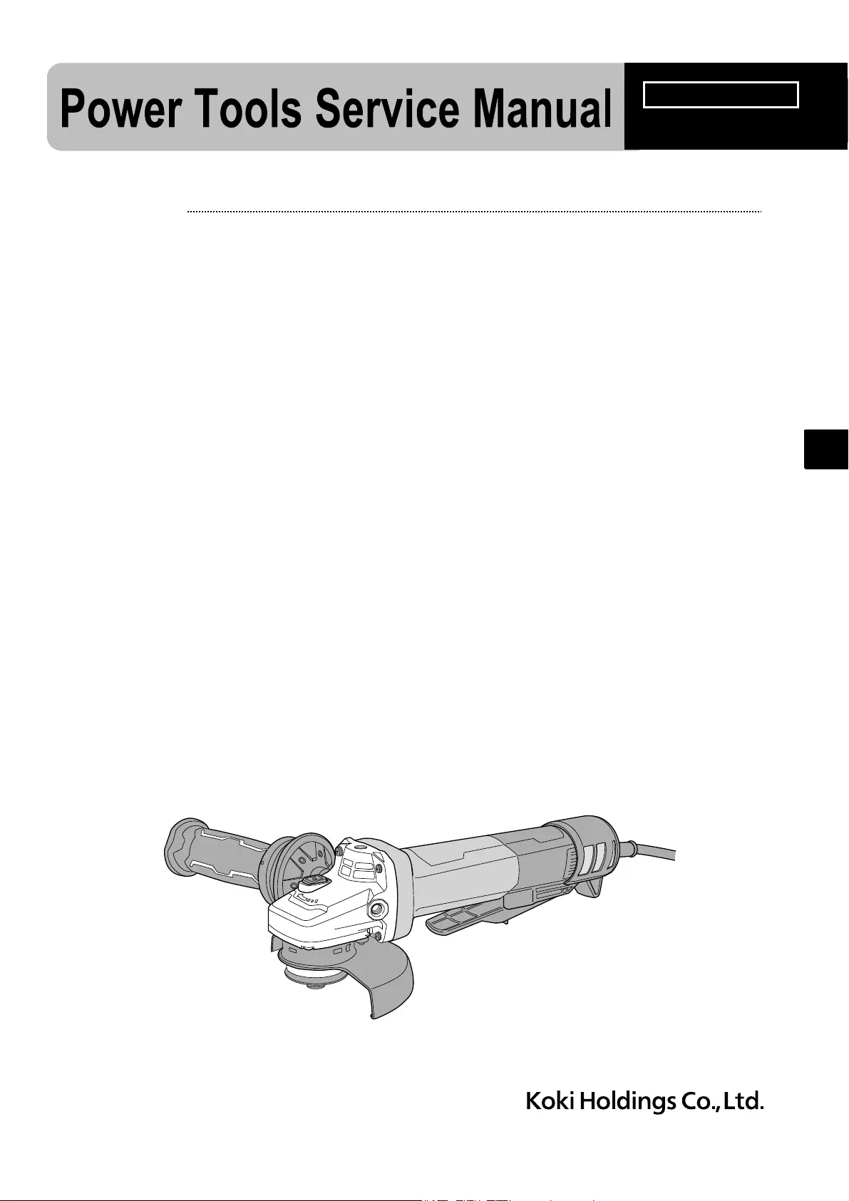
Electronic Disc Grinder
Models 100 mm (4”) G 10BYEQ2
115 mm (4-1/2") G 12BYEQ2
125 mm (5”) G 13BYEQ2
REPAIR GUIDE ---------------------------------------------------------------------------------------------------------------- 1
1. Precautions on disassembly and reassembly ----------------------------------------------------------- 1
• Disassembly ------------------------------------------------------------------------------------------------- 1
• Reassembly -------------------------------------------------------------------------------------------------- 4
• Lubrication point and type of lubricant ----------------------------------------------------------------- 6
• Tightening torque ------------------------------------------------------------------------------------------- 6
• Checking after reassembly ------------------------------------------------------------------------------- 6
• Insulation test ------------------------------------------------------------------------------------------------ 6
• No-load current value -------------------------------------------------------------------------------------- 7
• Connecting diagram ---------------------------------------------------------------------------------------- 7
CONTENTS Page
G
CONFIDENTIAL
Oct. 2022
Overseas Sales Management Dept.
G 13BYEQ2
-1-
Fig. 1
WARNING: Before disassembly, be sure to turn off the power switch and disconnect the power cord
plug from the outlet.
1. Precautions on disassembly and reassembly
[Bold] numbers in the description below correspond to the item numbers in the parts list and exploded
assembly diagram of the Model G 10BYEQ2, {Bold} numbers to those of the Model G 12BYEQ2, and
<Bold> numbers to those of the Model G 13BYEQ2.
1. Disassembly of the filter set
(1) Use a flat-blade screwdriver to unclip the two clips joining the bottom and side filters of the Filter Set
[45]{48}<48>.
(2) Push out the bottom filter in the arrow direction and remove the two side filters as shown in Fig. 1.
2. Removal of the rotor, stator, and controller
(1) Loosen the Tapping Screw (W/Flange) D4 x 16 (Black) [44]{47}<47> and pull out the Tail Cover Set
[43]{46}<46>.
(2) Loosen the four Tapping Screws (W/Flange) D4 x 23 (Black) [1]{1}<1> that fix the Gear Cover Ass’y
[3]{3}<3> and remove the Rotor [7]{7}<7> from the Housing [33]{36}<36> together with the Bearing
Holder [6]{6}<6>.
(3) Loosen the Special Nut M6 [4] or Special Nut M7 {4}<4> and remove the pinion.
(4) Insert the J-204 hooks (Code No. 970983) of the J-204 bearing puller (Code No. 970982) into the
clearance between the Ball Bearing 628DD [5]{5}<5> and Bearing Holder [6]{6}<6> from both sides,
and then fix the J-204 hooks in place with the wing bolts.
(5) Put the J-204 bearing puller on an appropriate stand. Push down the rotor shaft with a hand press to
remove the Ball Bearing 628DD [5]{5}<5>. Then remove the Bearing Holder [6]{6}<6>.
(6) Remove the insulating tape from the connector between the Sensor PCB [13]{13}<13> and Controller
[37]{40}<40>, then remove the connector. Remove the Fastons [12]{12}<12> of Stator Ass’y (A)
[11]{11}<11> from the Controller [37]{40}<40>. Remove silicone rubber from the connector.
NOTE: Be careful not to damage the connectors when removing.
(7) Loosen the Tapping Screw (W/Flange) D4 x 35 (Black) [36]{39}<39> and Tapping Screw (W/Flange) D4
x 20 (Black) [38]{41}<41>. Remove the Controller [37]{40}<40> from the Housing [33]{36}<36>.
(8) Remove the Fan Guide [10]{10}<10> from the Housing [33]{36}<36>. Remove Stator Ass’y (A)
[11]{11}<11> [33]{36}<36> from the Housing .
(9) Insert the hooks of the J-204 bearing puller (Code No. 970982) into the clearance between the Ball
Bearing 608DD [9]{9}<9> and Dust Seal [8]{8}<8>, and then fix the hooks in place with the wing bolts.
REPAIR GUIDE
Disassembly
Side filter
Bottom filter
Push out.
Unclip.
Flat-blade screwdriver
Unclip.
Side filter
-2-
(10) Put the J-204 bearing puller on an appropriate stand. Push down the rotor shaft with a hand press to
remove the Ball Bearing 608DD [9]{9}<9>.
(11) Remove the Dust Seal [8]{8}<8> from the rotor shaft.
3. Removal of the gear (Model G 10BYEQ2)
(1) Loosen the four Seal Lock Screws (W/Sp. Washer) M4 x 12 [21] and remove Packing Gland (A) [20]
from the Gear Cover Ass’y [3].
(2) Remove the Retaining Ring for D12 Shaft [15].
(3) Hold the bottom surface of Packing Gland (A) [20] and push down Spindle (A) [25] 2 or 3 mm with a
hand press as shown in Fig. 2.
(4) Hold Packing Gland (A) [20] in the reverse direction and push Spindle (A) [25] back to the original
position as shown in Fig. 3.
(5) Insert the J-128 gear puller (Code No. 970904) or an iron plate between the gear and Packing Gland (A)
[20]. Push out Spindle (A) [25] with a hand press as shown in Fig. 4.
NOTE: Replace the Ball Bearing 6001DD [17] with new one because it is deformed by the gear
pull-out force at disassembly.
Push
Fig. 2
Push
J-128 gear puller (Code No. 970904)
or an iron plate
Push
Fig. 3
Fig. 4


Product specificaties

Merk: Metabo
Categorie: Slijpmachine
Model: G13BYEQ2

Heb je hulp nodig?

Als je hulp nodig hebt met Metabo G13BYEQ2 stel dan hieronder een vraag en andere gebruikers zullen je antwoorden


Handleiding Slijpmachine Metabo

Handleiding Slijpmachine

Nieuwste handleidingen voor Slijpmachine