McIntosh MA7200 Handleiding


Lees hieronder de đź“– handleiding in het Nederlandse voor McIntosh MA7200 (36 pagina's) in de categorie Receiver. Deze handleiding was nuttig voor 20 personen en werd door 2 gebruikers gemiddeld met 4.5 sterren beoordeeld

Pagina 1/36
McIntosh Laboratory, Inc. 2 Chambers Street Binghamton, New York 13903-2699 Phone: 607-723-3512 www.mcintoshlabs.com
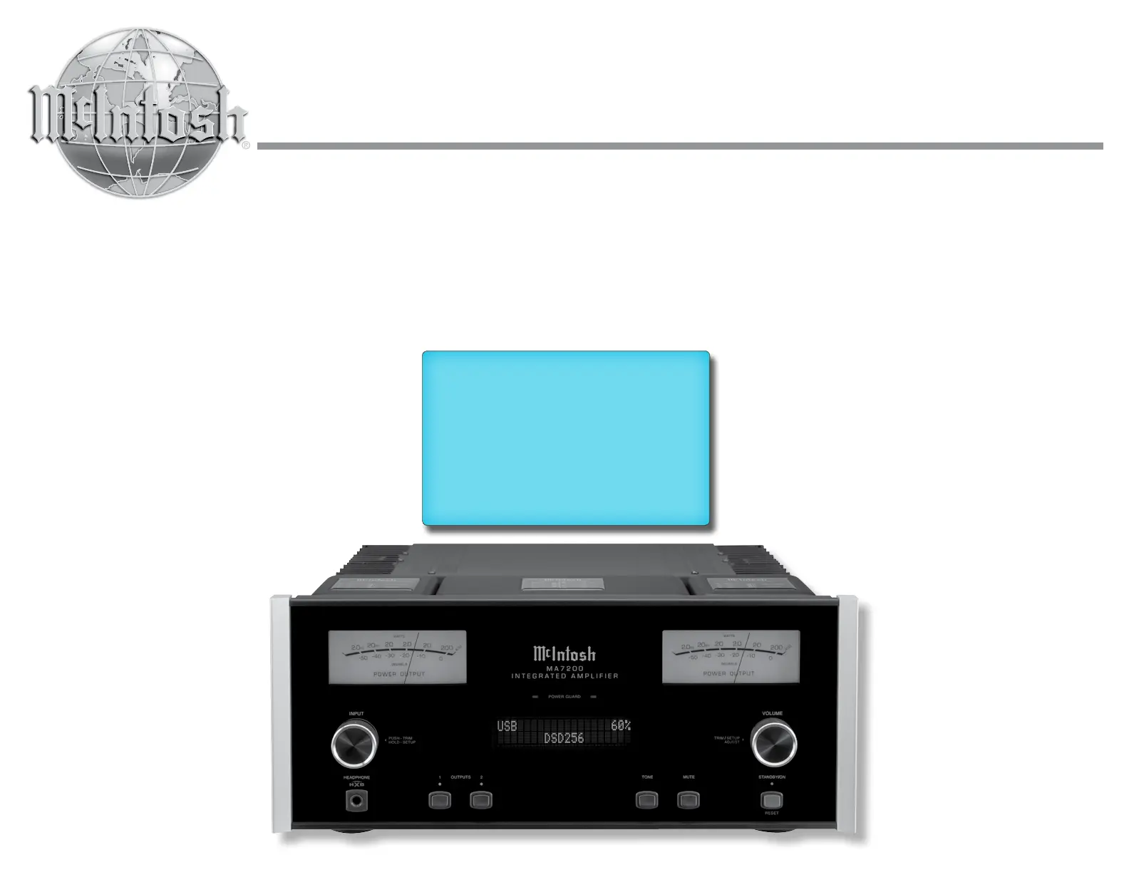
MA7200
Integrated Amplifier
Owner’s Manual
2
Your decision to own this McIntosh MA7200 Inte-
grated Amplifier ranks you at the very top among
discriminating music listeners. You now have “The
Best.” The McIntosh dedication to “Quality,” is as-
surance that you will receive many years of musical
enjoyment from this unit.
Please take a short time to read the information in
this manual. We want you to be as familiar as pos-
sible with all the features and functions of your new
McIntosh.
Copyright 2017 © by McIntosh Laboratory, Inc.
Table of Contents
Thank You
Please Take A Moment
Technical Assistance
If at any time you have questions about your McIntosh
product, contact your McIntosh Dealer who is familiar
with your McIntosh equipment and any other brands
that may be part of your system. If you or your Dealer
wish additional help concerning a suspected problem,
you can receive technical assistance for all McIntosh
products at:
McIntosh Laboratory, Inc.
2 Chambers Street
Binghamton, New York 13903
Phone: 607-723-3512
Fax: 607-724-0549
Customer Service
If it is determined that your McIntosh product is in
need of repair, you can return it to your Dealer. You
can also return it to the McIntosh Laboratory Service
Department. For assistance on factory repair return
procedure, contact the McIntosh Service Department
at:
McIntosh Laboratory, Inc.
2 Chambers Street
Binghamton, New York 13903
Phone: 607-723-3515
Fax: 607-723-1917
The serial number, purchase date and McIntosh Dealer
name are important to you for possible insurance
claim or future service. The spaces below have been
provided for you to record that information:
Serial Number: _______________________________
Purchase Date: _______________________________
Dealer Name: ________________________________
Important Safety Information is supplied in a separate document “Important Additional Operation Information Guide”
Safety Instructions .............................................................. 2
(Separate Sheet) ............................Important Additional
Operation Information Guide
Thank You and Please Take a Moment 2 ...............................
Technical Assistance and Customer Service 2 .......................
Table of Contents .................................................................2
General Information ............................................................3
Connector and Cable Information ....................................... 3
Introduction .........................................................................4
Performance Features .......................................................... 4
Dimensions ..........................................................................5
Installation ...........................................................................6
Connections:
Rear Panel Connections 7 .......................................................
(Separate Sheet) ...........................................................Mc1A
Connecting Components 8 .....................................................
Connection Diagrams (Separate Sheet) .................Mc2A/2B
Passthru Connections 9 ..........................................................
Connecting for Bi-Amplification ...................................... 10
Connecting Loudspeakers ............................................ 11-12
Remote Control and Front Panel:
Remote Control Push-buttons ........................................... 14
How to use the Remote Control ......................................... 15
Front Panel Displays, Controls,
Push-buttons and Jack ....................................................... 16
Setup Mode:
How to Operate the Setup Mode ....................................... 17
Setup Functions:
Default Settings .........................................................17
Firmware Version 17 ......................................................
Source Input Renaming ........................................ 17-19
Output Settings ..........................................................19
Power Control Triggers 1 and 2 .................................20
Data Ports ...................................................................20
Passthru ......................................................................21
Comm Port Baud Rate ...............................................21
Remote Control Codes ............................................... 21
IR Sensor ....................................................................22
Power Mode ...............................................................22
Factory Reset .............................................................22
Microprocessor Reset ........................................................23
Operation:
How to Operate the MA7200 .......................................24-31
Trim Functions:
Balance .......................................................................24
Tone Control...............................................................25
Trim Level ..................................................................25
Phono Adjustments ....................................................25
Mono/Stereo Mode ....................................................26
Meter Backlight .........................................................26
Display Brightness .....................................................26
Headphone HXD ........................................................27
Tone Control, Trim, Mute, Headphone Jack .............. 27
Power Output Meters, Power Guard ..........................27
Using a Separate Power Amplifier .............................28
Using Output 2 and Passthru ......................................28
Tone Controls ..............................................................29
Optical and Coaxial Digital Inputs ............................ 29
USB Input Operation with a Computer ...................... 30
Resetting the MA7200 to default settings ..................30
Photo .................................................................................. 32
Specifications................................................................33-34
Packing Instructions .......................................................... 35
3
on McIntosh Power Amplifiers. A 3.5mm stereo mini
phone plug is used for connection to the Power Con-
trol, Trigger and Passthru Outputs.
Data Port Connectors
The Data Out Ports send Remote
Control Signals to Source Compo-
nents. A 3.5mm stereo mini phone
plug is used for connection.
IR IN Port Connectors
The IR IN Port also uses a 3.5mm
stereo mini phone plug and allows the
connection of other brand IR Receiv-
ers to the MA7200.
RS232-C Data Port Cable
The RS232 Data Cable is a 3.5mm stereo mini phone
plug to a sub miniature DB 9 connector:
Output Terminal Connector
When cables with spade lugs are used
for Loudspeaker Connection, the spade
lugs need an opening of at least 3/10 inch
(7.6mm)
McIntosh Plug-In Jumper Connector
The MA7200 utilizes two phono style Plug-In Jumpers
to connect the Preamplifier Output to the
Power Amplifier Input.
Note: The Jumper Connector is available
from the McIntosh Parts Department:
McIntosh Jumper Connector Part No. 117781
XLR Connectors
Below is the Pin configuration for the XLR Balanced
Input Connectors on the MA7200. Refer to the dia-
gram for connection:
PIN 1: Shield/Ground
PIN 2: + Output
PIN 3: - Output
Power Control and Trigger Connectors
The Power Control Trigger Output Jacks send and
Passthru Input Jack receives Power
On/Off Signals (+12 volt/0 volt)
when connected to other McIntosh
Components. An additional connec-
tion is for controlling the illumina-
tion of the Power Output Meters
1. For additional connection information, refer to the
owner’s manual(s) for any component(s) connected
to the MA7200.
2. Apply AC Power to the MA7200 and other McIn-
tosh Component(s) only after all the system compo-
nents are connected together. Failure to do so may
cause a malfunction of system operations as the
Microprocessor’s Circuitry inside the components
is active when AC Power is applied.
3. The MA7200 includes an Auto Off Power Save
Feature and the default setting is enabled. For
additional information including how to disable it,
refer to page 22.
4. When Power Amplifier Protection Circuitry of
the MA7200 has activated, the Front Panel Power
Guard LEDs are illuminated continuously and the
sound will be muted.
5. When the Power Transformer has overheated due
to improper ventilation and/or high ambient operat-
ing temperature, AC Power is removed from the
MA7200. Normal operation will resume when the
operating temperature is in a safe range again.
6. For the best performance and safety, it is important
to always match the impedance of the Loudspeaker
to the Power Amplifier connections. Refer to pages
10 thru 12.
Note: The impedance of a Loudspeaker actually var-
ies as the Loudspeaker reproduces different
frequencies. As a result, the nominal impedance
rating of the Loudspeaker (usually measured at
a midrange frequency) might not always agree
with the impedance of the Loudspeaker at low
frequencies where the greatest amount of power
is required. Contact the Loudspeaker Manufac-
turer for additional information about the actual
impedance of the Loudspeaker before connecting
it to the McIntosh MA7200.
7. The MA7200 Remote Control is capable of operat-
ing other components. For additional information
go to www.mcintoshlabs.com.
8. The IR Input, with a 1/8 inch mini phone jack, is
configured for non-McIntosh IR sensors such as
a Xantech Model DL85K Kit. Use a Connection
Block such as a Xantech Model ZC21 when two
or more IR sensors need to be connected to the
MA7200. The signal from a connected External
IR Sensor will have priority over the signal from
the Front Panel IR Sensor.
9. When discarding the unit, comply with local rules
or regulations. Batteries should never be
thrown away or incinerated but disposed
of in accordance with the local regula-
tions concerning battery disposal.
10. For additional information on the
MA7200 and other McIntosh Products please visit
the McIntosh Web Site at www.mcintoshlabs.com.
Connector and Cable Information
Data
Signal
N/C
Data
Ground
General Information
Power
Control
Meter
Illumination
Control Ground
Main, Trig 1&2
and Pass-Thru
PIN 1 PIN 2
PIN 3
IR Data
Control
Ground
N/C
General Information, Connector and Cable Information
PIN 1
PIN 6
PIN 5
PIN 9
Data In
(DB9-pin2)
Ground
(DB9-pin5)
Data Out
(DB9-pin3)
DB9
(male connector)
3/10 of an inch
(7.6millimeters)


Product specificaties

Merk: McIntosh
Categorie: Receiver
Model: MA7200

Heb je hulp nodig?

Als je hulp nodig hebt met McIntosh MA7200 stel dan hieronder een vraag en andere gebruikers zullen je antwoorden


Handleiding Receiver McIntosh

Handleiding Receiver

Nieuwste handleidingen voor Receiver