JVC TM-H1700GU Handleiding
Bekijk gratis de handleiding van JVC TM-H1700GU (12 pagina’s), behorend tot de categorie Monitor. Deze gids werd als nuttig beoordeeld door 133 mensen en kreeg gemiddeld 4.7 sterren uit 67 reviews. Heb je een vraag over JVC TM-H1700GU of wil je andere gebruikers van dit product iets vragen? Stel een vraag
Pagina 1/12
TM-H1700G
OPERATING INSTRUCTIONS
Jan. 2002 No. 51922
[ TM-H1700G/E / TM-H1700G/U ]
BEDIENUNGSANLEITUNG : FARB-VIDEO-MONITOR
MANUEL D’INSTRUCTIONS : MONITEUR VIDEO COULEUR
MANUALE DI ISTRUZIONI : MONITOR VIDEO A COLORI
INSTRUCCIONES : MONITOR DE VIDEO A COLOR
!"#$%&'(&)
INSTRUCTIONS
TM-H1700G
COLOR VIDEO MONITOR
ESPAÑOL ITALIANO FRANÇAIS DEUTSCH ENGLISH
POWER
CHROMA MENU
INPUT SELECT
UNDER
SCAN
PHASE
TM-H1700G
BRIGHT
CONTRAST VOLUME/SELECT A B
LCT1092-001A-H
1101-Y-U-JMT
For Customer Use:
Enter below the Serial No. which is located on the rear of the cabinet.
Retain this information for future reference.
Pour l’usage du client:
Enter ci-dessous le numéro de série qui est situé sur l’arrière du coffret.
Conserver cette information pour une référence ultérieure.
Model No. :
Numéro de modèle : TM-H1700G
Serial No. :
Numéro de série :

1-2 No.51922
CONTENTS
SAFETY PRECAUTIONS ....................................
CONTROLS AND FEATURES ............................
HOW TO HANDLE BASIC OPERATIONS ..........
HOW TO USE THE MENU FUNCTIONS.............
HOW TO INITIALIZE THE SETTING ...................
BASIC CONNECTION EXAMPLE.......................
HOW TO USE EXTERNAL CONTROL ...............
TROUBLESHOOTING.........................................
SPECIFICATIONS ...............................................
SCREEN BURN
● It is not recommended to keep a certain still image displayed on screen for a
images on screen. This may cause a burning (sticking) phenomenon on the sc
not occur as far as displaying normal video playback motion images.
POWER CONNECTION
The power supply voltage rating of this product is AC 120 V (For U.S.A. and Cana
or United Kingdom), the power cord attached conforms to the following power su
cord designated to ensure Safety and EMC regulations of each countries.
Power cord
Power supply voltage : AC 120 V AC 230 V
Countries : U.S.A. and Canada European countries
Warning:
●
Do not use the same Power Cord for AC 120 V as for AC 230 V. Doing so may c
or fire.
Note for the United Kingdom power cord only
The plug on the United Kingdom power cord has a built-in fuse. When replacing
approved type, re-fit the fuse cover.
(Consult your dealer or qualified service personnel.)
How to replace the fuse
Open the fuse compartment with the blade screw driver, and
replace the fuse.
(* An example is shown in the illustration.)
In order to prevent any fatal accidents caused by misoperation
or mishandling the monitor, be fully aware of all the following
precautions.
WARNINGS
To prevent fire or shock hazard, do not expose this
monitor to rain or moisture. Dangerous high voltages
are present inside the unit. Do not remove the back
cover of the cabinet. When servicing the monitor,
consult qualified service personnel. Never try to service
it yourself.
WARNING : THIS APPARATUS MUST
BE EARTHED.
PRECAUTIONS
● Use only the power source specified on the unit.
(120 V AC/230 V AC, 50 Hz/60Hz)
● When not using this unit for a long period of time, or when
cleaning it, be sure to disconnect the power plug from the
AC outlet.
● Do not allow anything to rest on the power cord. And do not
place this unit where people will tread on the cord. Do not
overload wall outlets or power cords as this can result in a
fire or electric shock.
● Avoid using this unit under the following conditions:
– in extremely hot, cold or humid places,
– in dusty places,
– near appliances generating strong magnetic fields,
– in places subject to direct sunlight,
– in badly ventilated places,
– in automobiles with doors closed.
● Do not cover the ventilation slots while in operation as this
could obstruct the required ventilation flow.
● When dust accumulates on the screen surface, clean it with
a soft cloth.
● Unplug this unit from the AC outlet and refer servicing to
qualified service personnel under the following conditions:
– when the power cord is frayed or the plug is damaged,
– if liquid has been spilled into the unit,
– if the unit has been dropped or the cabinet has been
damaged,
– when the unit exhibits a distinct change in performance.
● Do not attempt to service this unit yourself as opening or
removing covers may expose you to dangerous voltage or
other hazards. Always refer servicing to qualified service
personnel.
● When replacement parts are required, have the service
personnel verify in writing that the replacement parts he/
she uses have the same safety characteristics as the
original parts. Use of manufacture’s specified replacement
parts can prevent fire, shock, or other hazards.
● Upon completion of any servicing or repair work to this unit,
please ask the service personnel to perform the safety
check described in the manufacturer’s service literature.
● When this unit reaches the end of its useful life, improper
disposal could result in a picture tube implosion. Ask
qualified service personnel to dispose of this unit.
This monitor is equipped with a 3-blade grounding-type
plug to satisfy FCC rule. If you are unable to insert the
plug into the outlet, contact your electrician.
Machine Noise Information Ordinance 3. GSGV,
January 18, 1991: The sound pressure level at the
operator position is equal or less than 70 dB(A)
according to ISO 7779.
Improper operations, in particular alternation of high
voltage or changing the type of tube may result in x-ray
emission of considerable dose. A unit altered in such a
way no longer meets the standards of certification, and
must therefore no longer be operated.
FCC INFORMATION (U.S.A. only)
CAUTION: Changes or modification not approved by
JVC could void the user's authority to operate the
equipment.
NOTE: This equipment has been tested and found to
comply with the limits for a Class B digital device,
pursuant to Part 15 of the FCC Rules. These limits are
designed to provide reasonable protection against
harmful interference in a residential installation. This
equipment generates, uses and can radiate radio
frequency energy and, if not installed and used in
accordance with the instructions, may cause harmful
interference to radio communications. However, there is
no guarantee that interference will not occur in a
particular installation. If this equipment does cause
harmful interference to radio or television reception,
which can be determined by turning the equipment off
and on, the user is encouraged to try to correct the
interference by one or more of the following measures:
– Reorient or relocate the receiving antenna.
– Increase the separation between the equipment and
receiver.
– Connect the equipment into an outlet on a circuit
different from that to which the receiver is connected.
– Consult the dealer or an experienced radio/TV
technician for help.
2
SAFETY PRECAUTIONS
Notice (U.S.A. only)
This product utilizes both a Cathode Ray Tube (CRT) and
other components that contain lead. Disposal of these
materials may be regulated in your community due to
environmental considerations. For disposal or recycling
information please contact your local authorities, or the
Electronics Industries Alliance: <http://www.eiae.org.>
1-3
No.51922
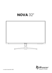
REMOTE (external control) terminal
Connect this terminal to an external control unit to enable
remote operation of the monitor.
Refer to the HOW TO USE EXTERNAL CONTROL on
page 15 for more details.
Video A terminals [VIDEO A IN/OUT]
Video signal input (IN) and output (OUT) terminals.
The output terminal is bridge-connected.
IN : Video signal input terminal
OUT : Bridge-connected video signal output terminal
Notes:
* For corresponding audio signals, use the AUDIO A
terminals
%
.
* Also refer to BASIC CONNECTION EXAMPLE
on page 13.
Video B terminals [VIDEO B IN/OUT]
Video signal input (IN) and output (OUT) terminals.
The output terminal is bridge-connected.
IN : Video signal input terminal
OUT : Bridge-connected video signal output terminal
Notes:
* For corresponding audio signals, use the AUDIO B
terminals
^
.
* Also refer to BASIC CONNECTION EXAMPLE on
page 13.
Video B (Y/C) terminals [VIDEO B Y/C IN/OUT]
Y/C (S-video) signal input (IN) and output (OUT) termi-
nals. The output terminal is bridge-connected.
IN : Y/C-separated (S-video) video signal input
terminal
OUT : Bridge-connected Y/C-separated (S-video) signal
output terminal.
REAR VIEW
<Rear Panel>
11
12
13
14
Notes:
* For cor
termina
* When b
the sam
* Also re
on page
Audio A
Input (IN
correspo
The outp
IN : A
OUT : B
Notes
* For cor
termina
* Also re
on page
Audio
Input (IN
signals c
VIDEO B
The outp
IN : A
OUT : B
Notes
* For cor
termina
* Also re
on page
15
12
11
13
14
15
16
VIDEO A
AUDIO A
AUDIO B
VIDEO B
IN OUT
IN
IN
IN
OUT
OUT
IN OUT
Y/C
OUT
16
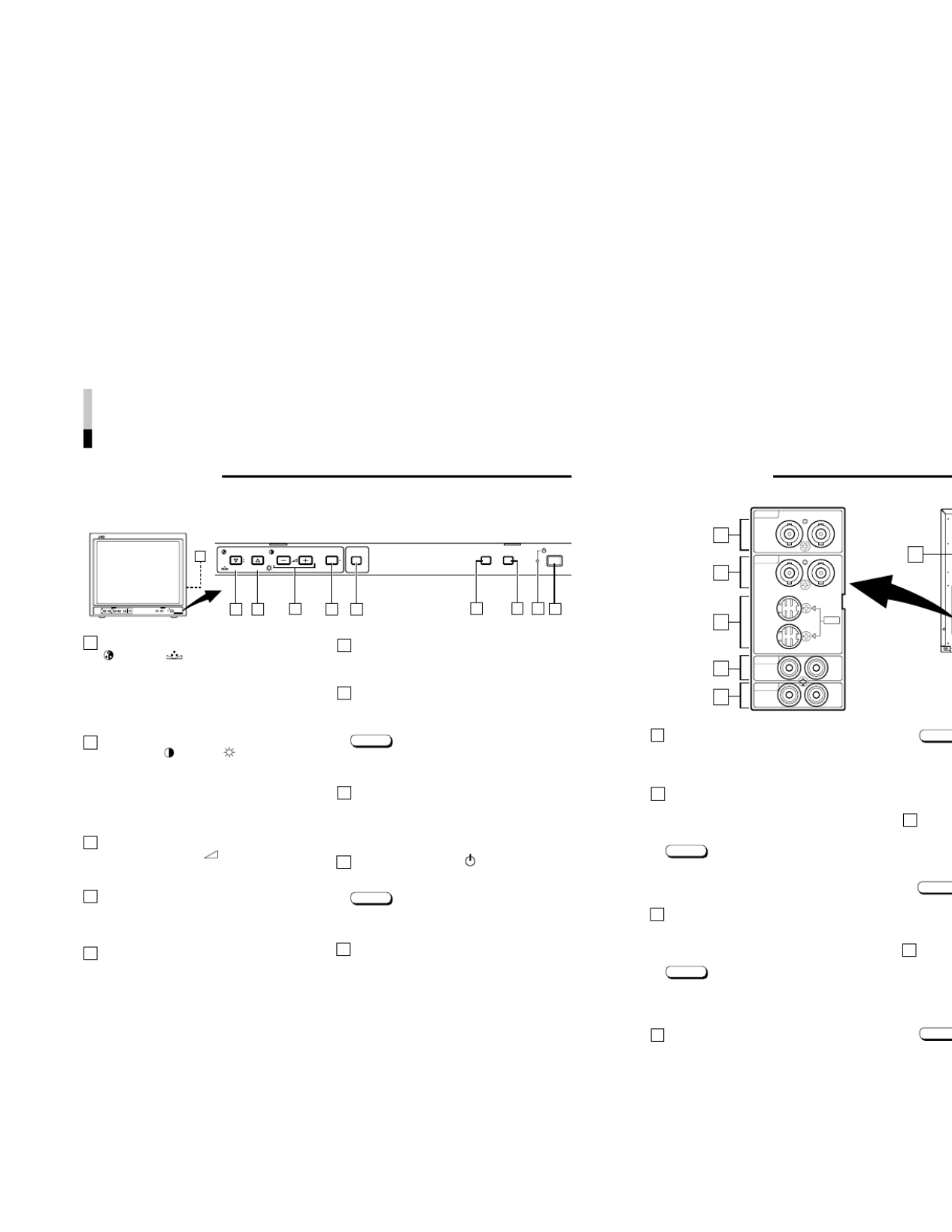
Chroma/Phase button
[ CHROMA/ PHASE]
Press this button to activate the picture color density
adjustment mode or picture hue adjustment mode. Each
time you press the button, the adjustment item changes.
Picture color density
f
Picture hue
Adjust the value with the VOLUME/SELECT buttons
3
.
Also used as a control button in the menu function mode.
Contrast/Brightness button
[CONTRAST / BRIGHT ]
Press this button to activate the picture contrast adjust-
ment mode or picture brightness adjustment mode. Each
time you press the button, the adjustment item changes.
Picture contrast
f
Picture brightness
Adjust the value with the VOLUME/SELECT buttons
3
.
Also used as a control button in the menu function mode.
Volume/Select buttons
[VOLUME/SELECT – +]
Adjusts the speaker volume. Also used as a control
button in the menu function mode.
Menu button [MENU]
Displays and disappears the <MENU> screen.
Pressing the CHROMA/PHASE button
1
with the Menu
button depressed will display the <SET-UP MENU>
screen.
Under Scan button [UNDER SCAN]
Reduces the screen size to display the entire image.
Press the button again to cancel Under Scan.
When selected, the Under Scan button lights.
CONTROLS AND FEATURES
FRONT VIEW
<Front Panel>
Input A (VIDEO) button [INPUT SELECT A]
Selects the video and audio signals input to the VIDEO A
@
and AUDIO A
%
terminals on the rear panel. The
button lights when selected.
Input B (VIDEO Y/C) button [INPUT SELECT B]
Selects the video and audio signals input to the VIDEO B
#
or VIDEO B (Y/C)
$
and AUDIO B
^
terminals on
the rear panel. The button lights when selected.
Note:
●The VIDEO B terminals include a video terminal (BNC
connector) and a Y/C terminal (mini-DIN 4-pin connec-
tor). The Y/C (S-video) terminal has priority.
Power indicator
Unlit : The main power is OFF.
Orange : The main power is ON, but the monitor’s power
is OFF (in the stand-by mode).
Green : The main power is ON, and the monitor’s power
is ON (in the normal operation mode).
Power switch [POWER ]
Press the power switch to turn the monitor’s power ON or
OFF when the main power is ON.
Note:
●When RUSH DELAY is set to SLOW, it takes about
three seconds before power is actually supplied after
the power switch is pressed.
Speaker
A built-in speaker is located inside the right side panel
when the monitor is viewed from the front.
1
2
3
4
5
6
7
8
9
10
4
687
POWER
CHROMA MENU
INPUT SELECT
UNDER
SCAN
PHASE
0C
BRIGHT
CONTRAST VOLUME/SELECT A B
94 5321
10
POWER
CHROMA MENU
INPUT SELECT
UNDER
SCAN
PHASE
TM-H1700G
BRIGHT
CONTRAST VOLUME/SELECT A B
Product specificaties
| Merk: | JVC |
| Categorie: | Monitor |
| Model: | TM-H1700GU |
| Gewicht: | 19600 g |
| Stroomvoorziening: | 120V AC (UL)/230V AC (CE) |
| Beeldschermdiagonaal: | 17 " |
| Frequentiebereik horizontaal: | 15.73 - 15.62 kHz |
| Frequentiebereik verticaal: | 59.94 - 50 Hz |
| Beeldverhouding: | 4:3, 16:9 |
| Aansluitingen: | D-sub 15-pin x1; BNC x 2; mini DIN 4-pin x 2 |
| Afmetingen (B x D x H): | 395 x 418 x 334 mm |
| Fosfor: | P-22 |
Heb je hulp nodig?
Als je hulp nodig hebt met JVC TM-H1700GU stel dan hieronder een vraag en andere gebruikers zullen je antwoorden
Handleiding Monitor JVC

14 Augustus 2024

9 Juli 2024

17 Mei 2024

4 Mei 2024

4 Mei 2024

1 Augustus 2023

1 Augustus 2023

5 Juni 2023

31 Mei 2023

27 Mei 2023
Handleiding Monitor
- Philips
- Orion
- Element
- Dough
- Alienware
- Sanyo
- Interlogix
- Flanders Scientific
- IBoardTouch
- Sonifex
- Triton
- Approx
- Hanwha
- Mobile Pixels
- Edifier
Nieuwste handleidingen voor Monitor
30 Juli 2025
30 Juli 2025
30 Juli 2025

30 Juli 2025

29 Juli 2025
29 Juli 2025

29 Juli 2025
29 Juli 2025
29 Juli 2025

29 Juli 2025