Indesit HI 50.B (WH) Handleiding
Bekijk gratis de handleiding van Indesit HI 50.B (WH) (68 pagina’s), behorend tot de categorie Oven. Deze gids werd als nuttig beoordeeld door 73 mensen en kreeg gemiddeld 4.9 sterren uit 37 reviews. Heb je een vraag over Indesit HI 50.B (WH) of wil je andere gebruikers van dit product iets vragen? Stel een vraag
Pagina 1/68

OVEN
HI 50.B
HI 50.B IX
HI 500.B
HI 500.B IX
HIN 550
HIN 550 IX
HIN 5S
HIN 5S IX
Contents
Installation, 2-4
Positioning
Electrical connections
Data plate
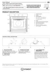
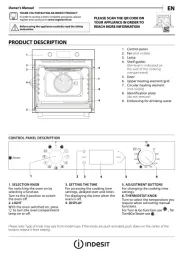
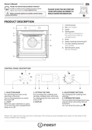
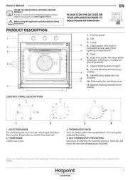
Description of the appliance, 5
Overall view
Control panel
Start-up and use, 6
Starting the oven
Using the cooking timer
Cooking modes, 7-8
Cooking modes
Practical cooking advice
Cooking advice table
Hob, 9
Type of hob
Switching on the glass ceramic hob
Practical advice on using the glass ceramic hob
Precautions and tips, 10
General safety
Disposal
Respecting and conserving the environment
Maintenance and care, 11
Switching the appliance off
Cleaning the appliance
Cleaning the oven door
Replacing the light bulb
Assistance
Operating Instructions
GB
Nederlands, 23English,1
Deutsch, 34 ÅëëçíéêÜ, 45
Français, 12
FR
GB
NL
DE GR
Espanol, 56
ES

2
GB
Before placing your new appliance into operation
please read these operating instructions carefully.
They contain important information for safe use, for
installation and for care of the appliance.
Please keep these operating instructions for future
reference. Pass them on to possible new owners of
the appliance.
Positioning
Keep packaging material out of the reach of
children.It can become a choking or suffocation
hazard (see Precautions and tips).
The appliance must be installed by a qualified
person in compliance with the instructions provided.
Incorrect installation may cause harm to persons,
animals or may damage property.
Fitting the appliance
Use the appropriate cabinet to ensure that the
appliance functions properly.
The panels adjacent to the oven must be made of
heat-resistant material.
Cabinets with a veneer exterior must be assembled
with glues which can withstand temperatures of up
to 100°C.
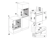
To install the oven under the counter (see
diagram) and in a kitchen unit, the cabinet must
have the following dimensions:
The appliance must not come into contact with
electrical parts once it has been installed.
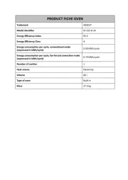
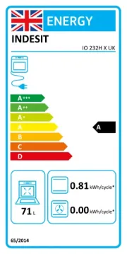
The consumption indications on the data plate have
been calculated for this type of installation.
Ventilation
To ensure good ventilation, the back panel of the
cabinet must be removed. It is advisable to install the
oven so that it rests on two strips of wood, or on a
completely flat surface with an opening of at least 45 x
560 mm (see diagrams).
Centring and fastening
Position the 4 tabs on the side of the oven according
to the 4 holes of the outer frame. Adjust the tabs
according to the thickness of the cabinet side panel,
as shown below:
thickness of 20 mm: take off
the removable part of the tab
( )see diagram
thickness of 18 mm: use the
first groove, which has already
been set in the factory (see
diagram)
thickness of 16 mm: use the
second groove (see diagram)
Secure the appliance to the cabinet by opening the
oven door and putting 4 screws into the 4 holes of the
outer frame.
All parts which ensure the safe operation of the
appliance must not be removable without the aid of a
tool.
595
558
min
45
min
575-585
min
560
+4 -0
480
+4 -0
555
580
500
39
15
595
23
572
543
543
543
543
543545
560 mm.
45 mm.
Installation

3
GB
Electrical connections
The cooker must be connected to the mains
electricity supply. It is designed to operate with
alternating current at the voltage and frequency
indicated on the data plate (see the following page).
The hob is connected to the cooker using a special
connector.
BUILT-IN HOB
BUILT-IN COOKER
WHITE RED
YELLOW
BLUE GREEN
Only on
certain models
Replace the metal protection after performing all the
necessary hob connections. If the hob is removed
from its position, the red cap which was originally
protecting the red connector must be replaced.
Fitting the power supply cable
1. Open the terminal
board by inserting a
screwdriver into the
side tabs of the cover.
Use the screwdriver as
a lever by pushing it
down to open the cover
(see diagram).
2. Loosen the cable
clamp screw and
remove it, using a
screwdriver as a lever
(see figure).
3. Remove the wire
contact screws L-N-
, then fasten the wires
under the screw heads,
respecting the colour
code: Blue (N), Brown
(L) and Yellow-Green
Verde ( ).
The terminal board is designed for a 400 V three-
phase connection (see diagrams below).
400V 3N~H05RR-F
5x2.5 CEI-UNEL 35363
If the electrical system has other characteristics (see
diagrams below), carry out the electrical connection
using the connection supports provided in the box
P.
230V 1N~H07RN-F 3x4
CEI-UNEL 35364
400V 2N~H05RR-F
4x2.5 CEI-UNEL 35363
3. Secure the power supply cable by fastening the
clamp screw.
4. Close the cover of the terminal board.
N L3 L1L2
1
3
2
4
5
N
L2
L3
L1
P
N L
1
3
2
4
5
N L2 L1
1
3
2
4
5
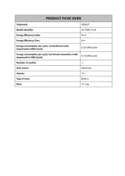
Product specificaties
| Merk: | Indesit |
| Categorie: | Oven |
| Model: | HI 50.B (WH) |
Heb je hulp nodig?
Als je hulp nodig hebt met Indesit HI 50.B (WH) stel dan hieronder een vraag en andere gebruikers zullen je antwoorden
Handleiding Oven Indesit

5 Juli 2025
5 Juli 2025
5 Juli 2025
4 Juli 2025
4 Juli 2025
4 Juli 2025
4 Juli 2025
4 Juli 2025
4 Juli 2025
11 Juni 2025
Handleiding Oven
- Steelmatic
- Wells
- Masterpro
- Gastroback
- Tisira
- Scancool
- Scholtes
- Morphy Richards
- Brentwood
- Ignis
- Costway
- Fisher And Paykel
- Rösle
- V-Zug
- FORS
Nieuwste handleidingen voor Oven

9 Augustus 2025
9 Augustus 2025
8 Augustus 2025
8 Augustus 2025
8 Augustus 2025

8 Augustus 2025
7 Augustus 2025
6 Augustus 2025

6 Augustus 2025
6 Augustus 2025