ICM Controls ICM517 Handleiding
ICM Controls Niet gecategoriseerd ICM517
Bekijk gratis de handleiding van ICM Controls ICM517 (1 pagina’s), behorend tot de categorie Niet gecategoriseerd. Deze gids werd als nuttig beoordeeld door 13 mensen en kreeg gemiddeld 4.9 sterren uit 6 reviews. Heb je een vraag over ICM Controls ICM517 of wil je andere gebruikers van dit product iets vragen? Stel een vraag
Pagina 1/1
ELECTRICAL SHOCK HAZARD
– Before installing this unit, turn off power at the main service panel by removing the fuse or
switching the appropriate circuit breaker to the OFF position.
LIAF212-2
LIMITED LIFETIME PROTECTION WARRANTY
Review enclosed warranty information for full details & registration information
The is UL Rated as a Type 2 device and must be installed ICM517
before the equipment it is intended to protect. It can be installed at
the A/C disconnect or an indoor/outdoor electrical panel. Suitable
for use on a circuit capable of delivering not more than 10,000
rms symmetrical amperes, 240V max, when protected by a circuit
breaker rated 20-60A maximum and 120V minimum. Device wires
should be kept at a minimal length to increase response time and
effectiveness of the control. Contains no serviceable parts.
Device is intended to be connected only to panel
connection. All wiring must conform to national, state
and local electrical codes. 14AWG wire or larger required.
Product contains no serviceable parts.
1. Turn off the main breaker and/or main power to the service disconnect.
2. Remove the cover on service disconnect or the electrical panel.
3. Mount through conduit connection of electrical panel:
3.1 Remove the retaining ring on the unit.
3.2 Feed the wires into the electrical panel service disconnect.
3.3 Re-secure the retaining ring.
4. Route the green wire to the grounding lug and secure.
5. Connect the two black wires and one white wire.
– For electrical panel: Connect to closest two-pole breaker.
– For A/C disconnect: Connect to the disconnect power terminals.
6. Reinstall cover on service disconnect or the electrical panel.
7. Restore power; LED(s) should be on with 120 VAC present from black
to green and black to white.
8. Close electrical panel or cover.
Instructions
Service Voltage: 120/240 volt, single phase
Maximum Surge Current: 100,000 amps
Maximum Energy Dissipation: 1,020 joules
Installation Point: Electrical panel, electrical disconnect
Diagnostics: Green light indicates surge suppression present
Enclosure: NEMA Type 3R waterproof metal enclosure
AC Protection Modes: L-L, L-N, L-G, N-G
Conduit Connection: 3/4”
Dimensions: 5.0” L x 2.78” W x 2.16” D
Weight: 0.55 lbs.
Specifications
Indoor Installation
(240 VAC Shown)
Outdoor Installation
(240 VAC Shown)
F
U
S
E
F
U
S
E
B
B
R
B
G
Ground
Wiring Diagram
To be performed by a licensed contractor/electrician only
•Apply120VACfromoneblackwiretothewhitewire;oneLED
shouldilluminate.
•Apply120VACfromtheotherblackwiretothewhitewire.One
LEDshouldilluminate.
•Apply120VACfrombothblackwirestothegreenwire,oneLED
shouldilluminate.
IfanyorallLEDsfailtoilluminate,theproductneedstobereplaced.
Maintenance Test Procedure
120 VAC Wiring
Black on hot leg
Black on hot leg
White on neutral leg
Green on earth ground
240 VAC Wiring
Black on hot leg
Black on hot leg
Green on earth ground
White capped off
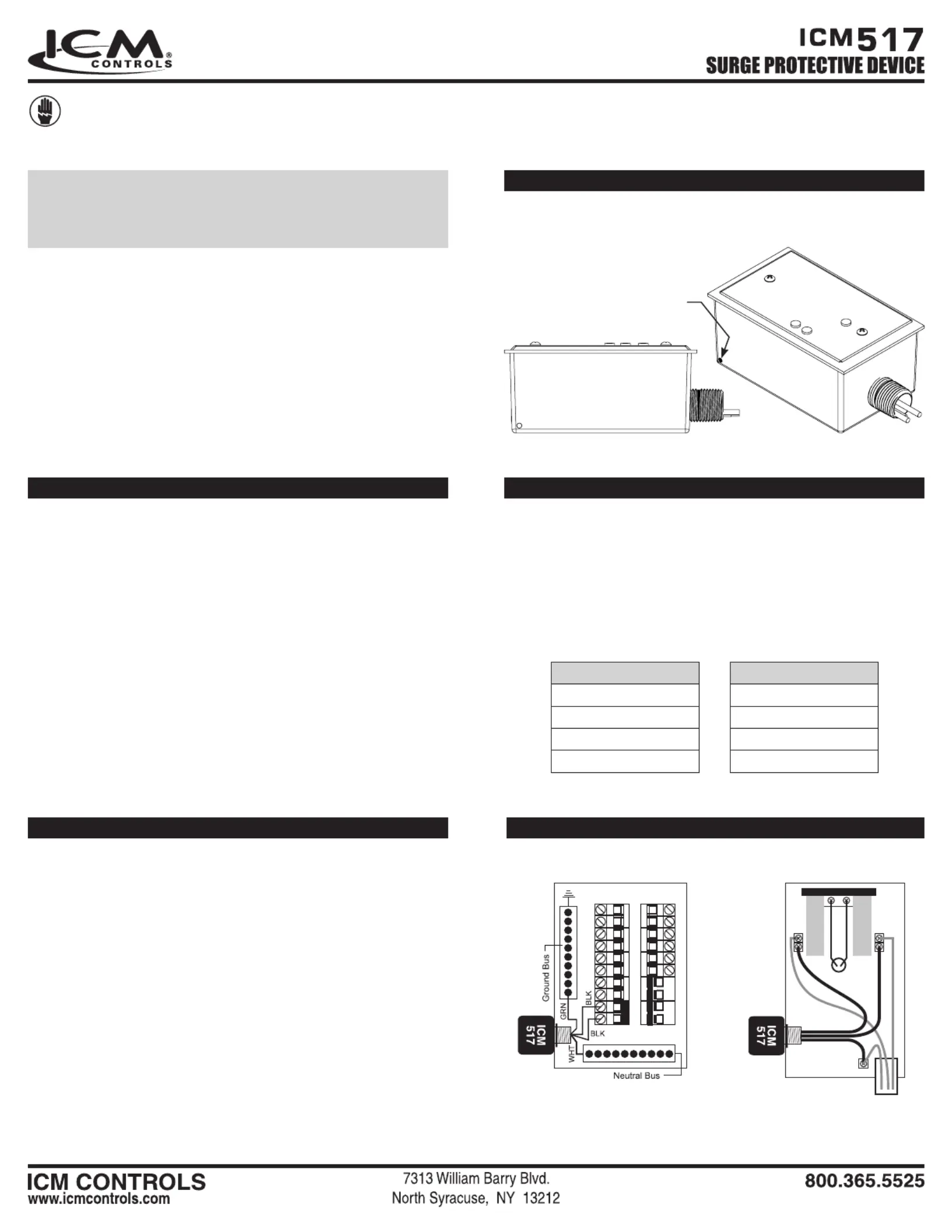
When used in Type 3R applications install drain hole using 1/8 dia.
drill, as shown , or the equivalent.
Drain Hole Information
Drainage Hole
Either Side
Product specificaties
| Merk: | ICM Controls |
| Categorie: | Niet gecategoriseerd |
| Model: | ICM517 |
Heb je hulp nodig?
Als je hulp nodig hebt met ICM Controls ICM517 stel dan hieronder een vraag en andere gebruikers zullen je antwoorden
Handleiding Niet gecategoriseerd ICM Controls

23 December 2025
20 December 2025
Handleiding Niet gecategoriseerd
Nieuwste handleidingen voor Niet gecategoriseerd
25 Augustus 2026
25 Augustus 2026
25 Augustus 2026
25 Augustus 2026
25 Augustus 2026
25 Augustus 2026
25 Augustus 2026
25 Augustus 2026
25 Augustus 2026
25 Augustus 2026