Hikvision DS-PDCL12-EG2 Handleiding
Hikvision Alarmsysteem DS-PDCL12-EG2
Bekijk gratis de handleiding van Hikvision DS-PDCL12-EG2 (8 pagina’s), behorend tot de categorie Alarmsysteem. Deze gids werd als nuttig beoordeeld door 95 mensen en kreeg gemiddeld 4.6 sterren uit 3 reviews. Heb je een vraag over Hikvision DS-PDCL12-EG2 of wil je andere gebruikers van dit product iets vragen? Stel een vraag
Pagina 1/8
WiredPIRCeilingDetector
DS-PDCL12-EG2
UserManual
EN50131-1:2006+A1+A2+A3
EN50131-2-2:2017
EnvironmentClassII
SecurityGrade2
TestedbyTÜVRheinland
HangzhouHikvisionDigitalTechnologyCO.,Ltd.No.555QianmoRoad,BinjiangDistrict,Hangzhou310052,China
English
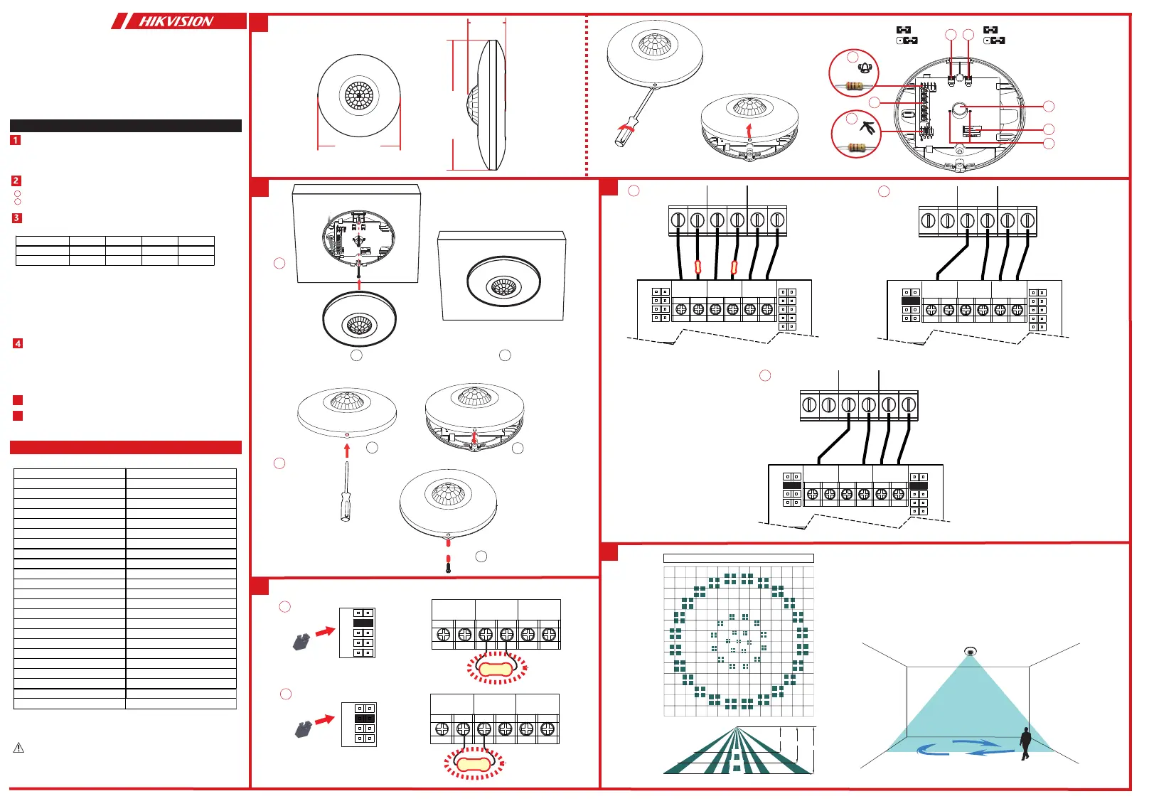
Appearance
Specification
5
6
ResistorWiring
ConnectionType
DetectionRange
PoweringOn
Note:Theresistormustbeconnectedinserieswithoneendofthe
detector.
a.NormallyClosed
b.SingleEndofLineWiring
c.DoubleEndofLineWiring
Afterpoweringon,theindicatorflashesrapidly.Oncethedetectorselftestis
completed,theLEDindicatorwillgooutuntilthedetectordetectsmovement.
RelayStatus
NormalPIRAlarmPIRFaultTamper
AlarmRelayCloseOpenOpenClose
TamperRelay
Close
CloseClose
Open
MountingbyExpansionScrew
ReinforcingBucklebyScrew(Optional)
a
b
UD23903B-E
PleaseusethepowersuppliescomplywiththerequirementsofEN50131-6at
theappropriategradeandenvironmentalclass.
Pleasedonotobscurethedetector’sfieldofviewpartiallyorcompletely.
Installation
1.TamperEOLpin2.Terminals3.AlarmEOLpin
4.LEDjumper5.Sensitivityjumper6.PIRsensor
7.Tamper8.LEDindicator
Method1:UsethejumpertoselectEOL(EndofLine)resistanceon
TAMPER/ALARMEOLpins.
Method2:AddtheresistortoTAMPER/ALARMwiringports.
Note:IfEOLwiringisnotused,leavethejumpersOFF.Donotforcethe
jumperifitisnotmatchedthepin.Method1&2shouldnotbeusedonthe
ALARM/TAMPERatthesametime.
a.AlarmResistance:1K,2K2,4K7,5K6,6K8
b.TamperResistance:1K,2K2,4K7,5K6
Detectionmethod
PassiveInfrared
Detectionrange12m
DetectionAngle360°
Detectionzones172
Detectablespeed0.3~2m/s
SensitivityAuto,low
Whitelightfilter6500lux
DigitaltemperaturecompensationSupport
CreepzoneprotectionSupport
DigitalprocessingSupport
SealedopticsSupport
TamperprotectionFront
LEDindicatorBlue(Alarm)
Powersupply9to16VDC
Typicalvoltage12VDC
Operationtemperature-10°Cto55°C(14°Fto131°F)
Storagetemperature-20°Cto60°C(-4°Fto140°F)
Operationhumidity10%to90%
Dimensionφ101.2mm×32.9mm
Weight109.5g
Mountingheight2.4to4m
MountingmethodCeiling
ApplicationscenarioIndoor
PowerConsumption13mAMax
2
1
12
a
2_KA3×25
a
=
=
4K7
2K2
1K
5K6
ALARM
+
-
EOL
TAMPER
EOL
2.2K
4K7
2K2
1K
5K6
6K8
ALARM
+
-
EOL
TAMPER
EOL
2.2K
b
ALARM
TAMPER
b
1
2
3
3
5
ZONE2
COM
ZONE1
COM
+
-
ALARMTAMPER
+-
6K8
5K6
4K7
2K2
1K
5K6
4K7
2K2
1K
ALARMTAMPER
EOLEOL
a
2.2K
2.2K
4
ZONE2
COM
ZONE1
COM
+
-
ALARMTAMPER
+-
6K8
5K6
4K7
2K2
1K
5K6
4K7
2K2
1K
ALARMTAMPER
EOLEOL
b
ZONE2
COM
ZONE1
COM
+
-
ALARMTAMPER
+-
6K8
5K6
4K7
2K2
1K
5K6
4K7
2K2
1K
ALARMTAMPER
EOLEOL
c
8
7
6
1
4
5
101.2mm
101.2mm
32.9mm
8m
10m
12m
2.4m
3m
4m
4m
2m
0m
6m
2m
4m
6m
6m6m4m4m2m2m0m
Zone:172
Plane:3
1K,2K2,
4K7,5K6
1K,2K2,
4K7,5K6,6K8
LEDON
LOW
LEDOFF
AUTO(Default)
2
3
Product specificaties
| Merk: | Hikvision |
| Categorie: | Alarmsysteem |
| Model: | DS-PDCL12-EG2 |
Heb je hulp nodig?
Als je hulp nodig hebt met Hikvision DS-PDCL12-EG2 stel dan hieronder een vraag en andere gebruikers zullen je antwoorden
Handleiding Alarmsysteem Hikvision

9 Maart 2026
1 Januari 2026
1 Januari 2026
30 September 2025
29 Maart 2025
29 Maart 2025
29 Maart 2025
18 December 2024
17 April 2024
17 April 2024
Handleiding Alarmsysteem
Nieuwste handleidingen voor Alarmsysteem
23 Juli 2026
23 Juli 2026
21 Juli 2026
10 Juli 2026
27 Mei 2026
5 Mei 2026
4 April 2026
2 April 2026
2 April 2026
1 April 2026