Hager 85745126 Handleiding
Hager Niet gecategoriseerd 85745126
Bekijk gratis de handleiding van Hager 85745126 (3 pagina’s), behorend tot de categorie Niet gecategoriseerd. Deze gids werd als nuttig beoordeeld door 66 mensen en kreeg gemiddeld 4.4 sterren uit 5 reviews. Heb je een vraag over Hager 85745126 of wil je andere gebruikers van dit product iets vragen? Stel een vraag
Pagina 1/3
KNX Radio shutter timer quicklink
Safety instructions
Electrical equipment must only be installed
and assembled by a qualied electrician in ac-
cordance with the relevant installation stan-
dards, regulations, directives and safety and
accident prevention directives of the country.
Failure to comply with these installation in-
structions may result in damage to the device,
re or other hazards.
The radio transmission is not suitable for safe-
ty or alarm applications.
These instructions are an integral component
of the product, and must be retained by the
end user.
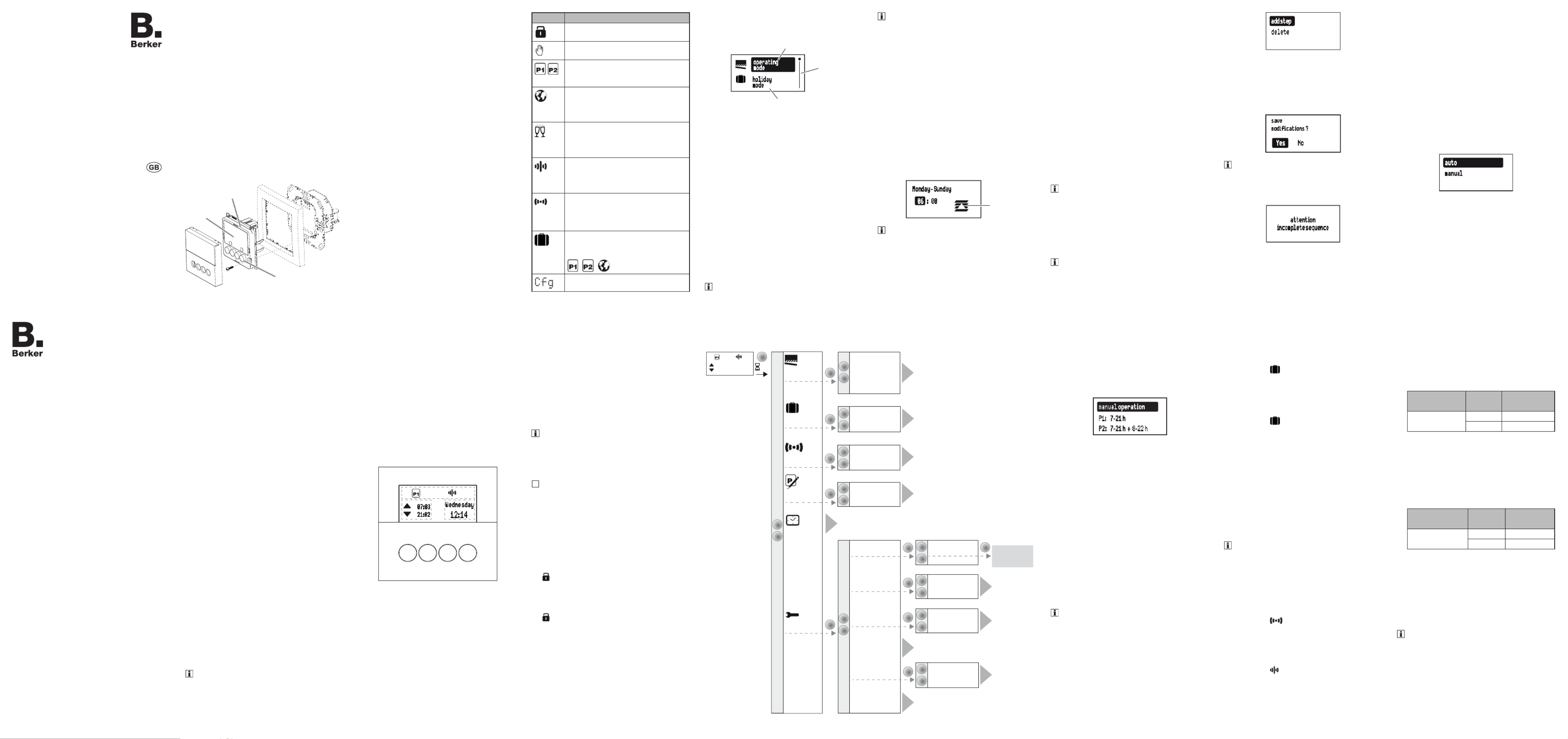
Design of the device
(3)
(5)
(6) (7)
(4)
(2)
(1)
Figure 1: Design of the device
(1) Insert (see „Accessories“, not in scope of
delivery)
(2) Frame (not in scope of delivery)
(3) Application module
(4) Display
(5) Design cover
(6) Screw for dismantling protection (not for
design lines R.1/R.3)
(7) Operation buttons
Function
This device is a product of the quicklink system, in
which installation devices communicate via radio
signals.
quicklink stands for a conguration mode in which
the function-related connection between trans-
mitters and receivers is set on the device through
push-buttons and displays without further tools.
All devices congurable by quicklink can be opera-
ted together in one system.
This device is compliant to the R&TTE-Directive
1999/5/EG. The Declaration of Conformity and
further system information can be found on our
homepage www.berker.de.
The device may be used in all EU and EFTA
countries.
Correct use
-Application module for shutter inserts or power
supply for radio application modules
-Manual, time-controlled and automatic operati-
on of blind/shutter motors connected to insert
-Transmission and reception of manual, time-
controlled and automatic operation commands
via quicklink
-Unsuitable for lighting control
-Only suitable for use in indoor areas, no drip or
spray water
The quicklink conguration of the devices must
only be carried out by qualied electricians.
Product characteristics
-quicklink functions for integration into the remo-
te and group control of blinds/shutters
-Integration into scenes
-Two preset standard time programmes, indivi-
dually adjustable
-Astro programme for automatic operation at
dawn/dusk
-Astro time shift to adjust the operation times
-Holiday programme for random operation times
in automatic mode
-Party programme to prevent unintentional ope-
ration of the shutters by automated operation
commands as well as radio/extension unit com-
mands
-Keylock
-Automatic switching to standard/daylight saving
time
-Brightness-dependent operation when using a
radio sun sensor
Performance after mains breakdown/return of
mains supply
-Mains breakdown:
Saving of the current conguration and pro-
gramming in the non-volatile memory. The de-
vice then switches to economy mode. Only the
internal clock continues to run to keep the time
up-to-date. The use of a buer memory en-
sures that the time stays up-to-date for up to 24
hours.
-Return of mains supply:
The application module executes an initialisati-
on operation1), the basic display is restored.
The stored conguration and programming is
loaded from the memory. Any operations pen-
ding when the power supply broke down will
not be executed after return of mains supply.
1)If the buer memory is full, date and time must be
entered again.
Operation
Operating concept and display elements
When controlling the shutter, the buttons (Fig. 2)
distinguish between a short press and a long press
of > 0.5 seconds on the button.
Pressing the button for > 2 seconds can trigger
various functions within the menu operation.
The current clock status is shown in the display.
Active functions are displayed by using symbols
(Table 1). Display illumination is activated for as
soon as a button is pressed.
OK
07 3:0
Wednesday
12 4:1
21 2:0
(8) (9)(11)(10)
(12)
(13)
(14)
Figure 2: Display and operating elements
(8) UP button p
(9) Back button á
(10) OK button
(11) DOWN button q
(12) Display area for weekday and time
(13) Display area for active functions/programming
(14) Display area for the next operation times
Symbol Function
Keylock active
Manual operation,
no automatic operation times
Preset programme (week programP1 -
me) or (week/weekend program-P2
me) is active
Astro programme is active,
UP and DOWN operation times are
controlled depending on dawn/dusk
times
Party programme is active,
manual operation only. Programmes,
extension units and radio commands
are not executed
Normal radio operation is active,
radio commands for master or group
controls can be transmitted and re-
ceived
Standalone programme,
Device has temporarily been removed
from higher-level master controls, but
can still be active in a group control
Holiday programme,
Random variation of operation times,
only possible in combination with
, ,
Device is in radio conguration mode
Table 1: Symbols in the function/programme line
(13) of the display
Operate shutter - operation from the basic
display
Manual shutter operation is possible at any time
from the basic display, even if automatic pro-
grammes are active. Operation may however be
locked (see locking/unlocking operation).
Press the or button.p q
Short press on button: Adjustment of the slat
position.
Long press on button (> 0.5 s): Lock, shutter
moves to nal position.
The max. operation time upon a long press on
the button is 2 minutes.
Short press on or button during the shut-p q
ter movement.
The shutter stops at the position reached.
If a protection signal (wind, rain) is present, no
move commands are executed (see Setting
Operating Mode).
Locking/unlocking operation
The operation buttons of the shutter timer can be
locked, in order to prevent unintentional operation,
e.g. by children.
The shutter timer shows the basic display.
Press the button for more than 5 seconds.á
is shown in the display. The operation but-
tons are locked.
Press the button again for more than 5 á
seconds.
disappears in the display. The operation
buttons are enabled.
Opening the menu and navigating
The shutter timer is set and programmed via the
menu.
o peratin g
m ode
h olid a y
mode
(17)
(15)
(16)
Fig. 3: Main menu
(15) Selected menu item
(16) Position display of the selected menu item in
the list of options
(17) Next option in the list
Short press on any button.
Operation is activated. The display is illuminated.
Press the button for more than 2 seconds.OK
The main menu is displayed. The rst menu
item (Fig. 3, 15) is highlighted operating mode
dark.
Press the or button to navigate through p q
the menu.
The selected menu item is highlighted dark.
Conrm the selected option by pressing OK.
The submenu opens.
Navigation through the menus can continue as
described above.
Press the button.á
The display switches to the previous contents.
To return to the basic display, press the á
button multiple times as necessary.
manual operation
P1: 7 - 21h
P2: 7 - 21h + 8 - 22h
(astro mode)
party mode
(activation)
(deactivation)
Deutsch
English
Francais
country-city selection
coordinates
OK
>2 s
OK
OK
language
time settings
astro settings
factory settings
summer/winter time
operating
mode
holiday
mode
program
settings
time / date
modify
(restore defaults)
OK
advanced
settings
OK
OK
OK
OK
OK
OK
standalone
mode
(activation)
(deactivation)
configuration
select quicklink
function
quicklink settings
OK
0 73: 0
Wednesday
1 24: 1
2 12: 0
display settings
Displayed in
selected language
(e.g.: English)
A1
(18) (19)
(20)
(21)
(22)
(23)
(26)
(27)
(25)
A2
A5
A6
A7
E1
A8
A9
A3
A4
Figure 4: Menu overview
If no button is pressed for a period of two mi-
nutes, the display returns to the basic display.
Figure 4 shows an overview of the functions in the
menus/submenus: for the user andfor the A.. E..
electrician refer to sections for additional informa-
tionMenu items in brackets are visible depending .
on the timer programming status.
Setting the values
Values, such as time or date, have to be set rst
for the programming of some functions.
The value to be set is selected and is highlighted
dark.
Press the or button.p q
Short press on button: Change the value by
one step.
Keep button pressed: Scroll through values.
Scrolling stops when the button is released.
M o n d a y - S u n d a y
0 6 : 00
(28)
If operation times are set, then a symbol (28)
shows whether it is an UP or DOWN operation
time.
Press the button.OK
The set value is applied.
Press the button.á
The display switches to the previous value. The
setting is not applied.
Submenu A1 - Select programme
One can choose between the following pro-
grammes:
-: manual operation
Operation takes place solely using the buttons
(see Operate shutter - operation from the basic
display).
-Time programmes and P1: 7 - 21 hP2: 7 - 21
h + 8 - 22 h :
These programmes are factory preset but can
be changed individually.
P1 is a week programme with identical operati-
on times for each day, is a week/weekend P2
programme with dierent operation times for
Mon. - Fri. and Sat. - Sun.
- astro mode:
Programme for dawn/dusk-dependent control
of the shutters (see submenu A7 - Setup Astro
programme).
The astro mode is only displayed if it has been
set up.
-: party mode
The Party programme prevents unintentional
operation of the controlled blinds/shutters by
programmed operation time or extension unit
operation, e.g. to prevent people from being
shut out by the shutter going down.
When the Party programme is active, a blind/
shutter can only be operated manually using
the buttons on the timer. Control of the shutter
via high-level control-sections and sensors as
well as by extension units, radio and forced
control commands is deactivated.ontrol of the
shutter by higher-level control-sections and
sensors as well as by extension units, radio
and forced control commands is deactivated.
If the blind/shutter was moved to a dened po-
sition in (see Table 4) and this forced mode
forced mode is active, then the Party pro-
gramme cannot be selected.
The shutter timer shows the Programme selection
submenu (Fig. 4, 19). The most recently selected
programme is highlighted dark.
man ua l op erat io n
P 1: h 7- 21
P 2: h+ h 7- 21 8- 22
Press the or button to select the desired p q
programme.
Press the button.OK
The screen switches to the basic display. The
selected programme is run, the corresponding
symbol (Table 1) is shown in the display (Fig.
2, 13).
Submenu A2 - Change, delete or add to
programmes
The options and (Figure modifyrestore defaults
4, 22) can be used for the preset factory pro-
grammes:
- to adapt, add to or delete operation modify
times. A maximum of 20 operation times per
day are possible.
--restore defaults to reset a modied pro
gramme to the factory default programming.
Switching times can only be edited individually
under . It is not possible to edit pro-modify
gramme blocks (e.g. Mon. - Fri.).
Press the or button to select options or to p q
change the values.
Press the button.OK
Short press on button: Conrmation of the
current selection or the set value.
Long press on button (> 2 s) in programme edi-
ting: Adding an extra switching time or deletion
of an existing switching time.
a dd s t ep
delete
Press the button.á
Short press on button: The display switches to
the last content.
Long press on button (> 2 s): Programming is
completed, the switching times are skipped.
Changes can be saved or rejected.
save
m odifications ?
Ye s N o
Should no DOWN operation time follow an UP
operation time, or vice-versa, then the user is
informed on the display before saving, that
switching times are missing. Saving is never-
theless possible.
attention
i n co m p le t e s eq u e nc e
Submenu A3 - Activating/deactivating Holiday
programme
The Holiday programme is a simple form of the
presence simulation. The operation times of an
existing programme (P1, P2, Astro) are varied,
randomly, by ± 15 minutes. If operation times are
too close together (dierence < 15 minutes), then
they are not varied.
The shutter timer can be found in the submenu
holiday mode (Fig. 4, 20).
Conrm activation with .OK
The screen switches to the basic display and
the symbol for is displayed holiday mode
(Fig. 2, 13).
or:
Conrm deactivationwith .OK
The screen switches to the basic display and
the symbol for is hidden in holiday mode
the display.
Submenu A4 - Activating/deactivating Stand-
alone programme
The Stand-alone programme can be used for
radio installations, in which the shutter timer was
assigned to a master shutter control as a subordi-
nate control. In Stand-alone operation the device
ignores the radio commands of higher-level master
controls and forced control commands, as well as
extension unit signals, i.e. operation commands
concerning the local blind/shutter are not execut-
ed.
If the blind/shutter was moved to a dened po-
sition in (see Table 4) and if this forced mode
forced mode is active, then the Stand-alone
programme cannot be selected.
The shutter timer can be found in the submenu
standalone mode(Fig. 4, 21).
Conrm activationOK with .
The screen switches to the basic display and
the symbol for is displa-standalone mode
yed (Fig. 2, 13).
or:
Conrm deactivationOK with .
The screen switches to the basic display and
the symbol for normal radio operation
is displayed (Fig. 2, 13).
Submenu A5 - Set time/date
In the main menu (Fig. 4, 18), is high-time/date
lighted dark.
Short press on button.OK
The hour display as an active element is high-
lighted dark.
Set the date and time (see Setting values).
When all the setting options have been run
through, the screen returns to the basic display.
Submenu A6 - Set time options
The automatic switching to standard/daylight
saving time can be activated or deactivated for the
shutter timer.
The submenu is displayed (Fig. 4, time settings
25).
Conrm the summer/winter time option by
pressing .OK
a u t o
m a n u a l
Press the buttons or to select the required p q
setting and conrm by pressing OK.
The device applies the setting and returns to
the submenu .time settings
Submenu A7 - Setup Astro programme
The Astro programme leads to a dusk/dawn depen-
dent control of shutters, meaning that automatic
operation time adjustment occurs according to the
season. As these operation times can be very early
or very late, the Astro programme oers enhanced
options in order to adapt the operation time.
-Deviation from dawn time by ± 120 minutes
-Deviation from dusk time by ± 120 minutes
-Earliest UP operation time () earliest up time
No operation times are executed before the
earliest UP time,as dened by dawn. The blind
moves UP at the time set here.
Astro operation times after the set time are
executed normally.
Example:
Set time
earliest up time
SunriseExecuted
operation time
06:15 07:32 07:32
05:23 06:15
-Latest DOWN operation time (latest down ti-
me)
No operation times are executed after the latest
DOWN operation time, as dened by dusk. The
shutter moves DOWN at the time set here.
Astro operation times before the set time are
executed normally.
Example:
Set time
latest down time
SundownExecuted
operation time
20:00 17:42 17:42
21:12 20:00
The installation location must be set to determine
the correct Astro operation times.
-Country/city selection:
Simple setting option by selecting a country
and a city near the location from a comprehen-
sive list of European cities.
-The setting is made by entering the geographic
co-ordinates and time zone of the location.
If the location is outside Europe or a high level
of accuracy is required for the Astro operation
times, then the setting should be made using
the co-ordinates.
The submenu is displayed astro settings
(Fig. 4, 26).
Press the buttons or to select the setting p q
type and conrm by pressing OK.
The country/city selection and the co-ordinate
settings are displayed.
Operation and
installation instructions
Berker GmbH & Co. KG
Zum Gunterstal
66440 Blieskastel/Germany
Tel.: + 49 6842 945 0
Fax: + 49 6842 945 4625
E-Mail: info@berker.de
www.berker.com
05/2022
6LE008041A
KNX radio shutter timer quicklink
Order-No. 8574 51 ..
Product specificaties
| Merk: | Hager |
| Categorie: | Niet gecategoriseerd |
| Model: | 85745126 |
| Kleur van het product: | Antraciet |
| Internationale veiligheidscode (IP): | IP20 |
| Bedrijfstemperatuur (T-T): | -5 - 45 °C |
| Relatieve vochtigheid in bedrijf (V-V): | 0 - 65 procent |
| Aantal producten inbegrepen: | 1 stuk(s) |
Heb je hulp nodig?
Als je hulp nodig hebt met Hager 85745126 stel dan hieronder een vraag en andere gebruikers zullen je antwoorden
Handleiding Niet gecategoriseerd Hager

12 Mei 2025
12 Mei 2025
12 Mei 2025
12 Mei 2025
12 Mei 2025
12 Mei 2025
12 Mei 2025
12 Mei 2025
12 Mei 2025
12 Mei 2025
Handleiding Niet gecategoriseerd
Nieuwste handleidingen voor Niet gecategoriseerd
24 Juli 2026
24 Juli 2026
23 Juli 2026
23 Juli 2026
23 Juli 2026
23 Juli 2026
23 Juli 2026
23 Juli 2026
23 Juli 2026
23 Juli 2026