Growatt ATS-S Handleiding
Growatt Niet gecategoriseerd ATS-S
Bekijk gratis de handleiding van Growatt ATS-S (2 pagina’s), behorend tot de categorie Niet gecategoriseerd. Deze gids werd als nuttig beoordeeld door 18 mensen en kreeg gemiddeld 4.2 sterren uit 5 reviews. Heb je een vraag over Growatt ATS-S of wil je andere gebruikers van dit product iets vragen? Stel een vraag
Pagina 1/2
1.1.
ATS-S
User Manual
Introduction
The Auto-Transfer Switch Single Phase (ATS-S)controls the switching of the contactors to provide power to the EPS load in both grid-tied
and off-grid conditions. The ATS-S integrates a contactor to provide users with a simple connection. It is used with Growatt Hybrid inverter
and AC coupled inverter (single phase).Configured with ATS-S, when the power outage, ATS-S can automatically switch to Off-Grid state,
it can continue to supply power to the EPS load, the load can continue to run.
2.
The location of ATS in the system-S
8.
4.
General Information - Parts List
3.
Configuration
7.
9.
ModelName
Growatt ATSS-
Grid Normal Voltage
230V 50/60Hz
Grid Max Current
30A
EPS Normal Voltage
230V 50/60Hz
EPS Max Current
30A
Load Normal Voltage
230V 50/60Hz
Load Max Current
30A
Cooling Concept
Natural
Ingress Protection
IP65
Installation
Wall Mountable
-25℃ ~ +50℃
Compatible Model
Operation Ambient
Temperature
Growatt Hybrid inverter and AC
coupled inverter (single phase )
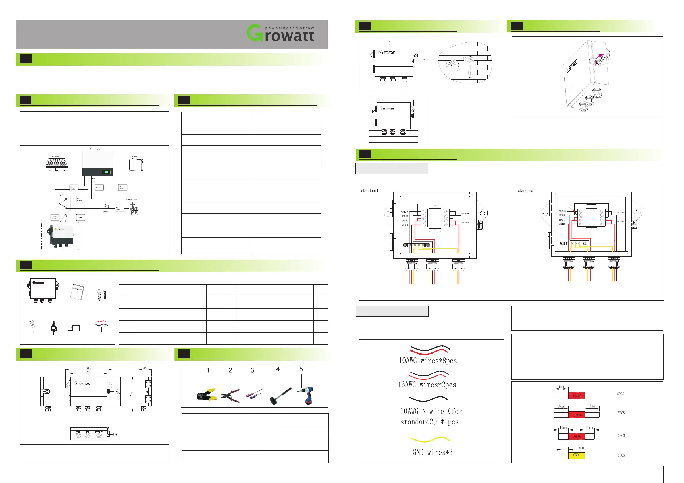
Opening step of ATS-S
Open the ATS-S
As shown above, please put the key into the Keyhole on the ATS-S
right, clockwise rotation of 90°, the lower end of the first lock up
gently move Open, remove the lock at the upper end of the buckle,
then you can open the cover,Step of locking the cover opposite to
the above.
Wiring Connection
There are two type wire connection diagram of ATS, show as below:-S
9.1 total wire diagram
As shown in chart 2.1, the input side ATS-S is connected with
EPS and GRID of SPH/SPA inverter, the output side is connected
with EPS LOAD, and the position in the system is shown in the
circle in the chart 2.1. EPS LOAD default connect with Grid
power, if Grid is lost, EPS LOAD will turn to EPS output of hybrid
inverter.
A
B
C
D
E
F
G
ItemItemItem NameItem Name
QtyQty
ATS-S (Auto-Transfer Switch
Single Phase )
User Manual
Anchor Bolt
O -type terminal
1
2
1
10
22
3
Key
Cold pressed terminal(large /small)
Contactor control line
Part ListPart List
5.
Dimension & Weight
Dimension (L x W x H):312*237*85mm
Weight : 2.38KG
6.
Tool
NONO
1
2
3
4
5
DescriptionDescription
Pipe clamp
Diagonal plier
Screwdriver
Rubber hammer
Driller
1.To leave at least 300mm
space from ATS-S
2.Make the position of 2
holes(282mm) .
3.Drill holes with φ10 drill
Depth: at least 40mm.
a
b
c
1. Wires below are needed before installation(16AWG wire
has been configured in accessory bag).
9.2 wires making
2.Use the diagonal plier to trip 15mm of insulation from one side of
the 10AWG wires(6pcs);
Use the diagonal plier to trip 15mm of insulation from two side of
the 10AWG wires (2pcs,If it is standard 2, you need 3pcs);
Use the diagonal plier to trip 10mm of insulation from two side of
the 12AWG wires(2pcs);
Use the diagonal plier to trip one side of GND wire about
7mm(3pcs).
2
Note:
1.These include 2pcs 10AWG wire (1pcs red, 1pcs black) for
shorting contactor ports 2 and 4, 6 and 8, Its length is about 60cm,
10 AWG N wire (for standard2)length is about 50cm.
Standard 1 is for general using, and standard 2 is for like Australia where Neutral line can't be switched. When connect with ATSS,
please check which standard is suit for you.
-
A
B
C
D
E
F
G
300mm
300mm
300mm
300mm
Product specificaties
| Merk: | Growatt |
| Categorie: | Niet gecategoriseerd |
| Model: | ATS-S |
| Kleur van het product: | Black, White |
| Gewicht: | 2380 g |
| Breedte: | 250 mm |
| Diepte: | 85 mm |
| Hoogte: | 200 mm |
| Stroom: | 30 A |
| Vormfactor: | Wandmontage |
| AC-ingangsfrequentie: | 50/60 Hz |
| Bedrijfstemperatuur (T-T): | -25 - 50 °C |
| Ingang operation voltage (min): | 230 V |
| Ingang operation voltage (max): | 400 V |
Heb je hulp nodig?
Als je hulp nodig hebt met Growatt ATS-S stel dan hieronder een vraag en andere gebruikers zullen je antwoorden
Handleiding Niet gecategoriseerd Growatt

13 Maart 2026
21 December 2025
11 December 2025
10 December 2025
10 December 2025
9 December 2025
9 December 2025
9 December 2025
9 December 2025
9 December 2025
Handleiding Niet gecategoriseerd
Nieuwste handleidingen voor Niet gecategoriseerd
11 Juni 2026
11 Juni 2026
11 Juni 2026
11 Juni 2026
11 Juni 2026
11 Juni 2026
11 Juni 2026
11 Juni 2026
11 Juni 2026
11 Juni 2026