Fluke i200 Handleiding
Bekijk gratis de handleiding van Fluke i200 (2 pagina’s), behorend tot de categorie Niet gecategoriseerd. Deze gids werd als nuttig beoordeeld door 194 mensen en kreeg gemiddeld 4.3 sterren uit 97.5 reviews. Heb je een vraag over Fluke i200 of wil je andere gebruikers van dit product iets vragen? Stel een vraag
Pagina 1/2

®
i200/i200s
AC Current Clamp
Instruction Sheet
Introducing the i200/i200s
The i200 is a single range 200A clamp-on AC Current Clamp with
current output via safety shrouded banana plugs.
The i200s is a dual range 20A and 200A clamp-on AC Current
Clamp with voltage output via a safety insulated BNC connector.
A dual banana to BNC adapter is supplied to allow the i200s to be
connected to multimeters with banana input.
Unpacking
The following items should be included in your Current Clamp box:
• Current Clamp
• Dual Banana to BNC Adapter model PM9081 (only with i200s)
• Instruction Sheet (this paper)
Check the contents of the shipping box for completeness. If
something in the box has been damaged or missing, contact your
distributor or the nearest FLUKE sales or service office immediately.
Safety Information
Read First: Safety Information.
To ensure safe operation and service of the
current clamp, follow these instructions:
• Read the operating instructions before use and follow all safety
instructions.
• Use the Current Clamp only as specified in the operating
instructions, otherwise the clamp’s safety features may not
protect you.
• Adhere to local and national safety codes. Individual protective
equipment must be used to prevent shock and arc blast injury
where hazardous live conductors are exposed.
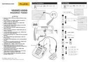
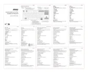
• Do not hold the Current Clamp anywhere beyond the tactile
barrier, see Figure 1.
• Before each use, inspect the Current Clamp. Look for cracks or
missing portions of the clamp housing or output cable
insulation. Also look for loose or weakened components. Pay
particular attention to the insulation surrounding the jaws.
• Check the magnetic mating surfaces of the clamp jaws; these
should be free of dust, dirt, rust and other foreign matter.
• Never use the clamp on a circuit with voltages higher than 600
V CAT III.
− CAT III equipment is designed to protect against transients
in equipment in fixed equipment installations, such as
distribution panels, feeders and short branch circuits, and
lighting systems in large buildings.
• Use extreme caution when working around bare conductors or
bus bars. Contact with the conductor could result in electric
shock.
• Use caution when working with voltages above 60 V dc, 30 V ac
rms or 42 V ac peak. Such voltages pose a shock hazard.
Figure 1. Safely holding the Current Clamp
Symbols
May be used on HAZARDOUS LIVE
conductors.
Product is protected by double insulation.
Risk of Danger. Important information. See
Instruction Sheet.
Risk of Electric Shock.
Conforms to relevant European standards.
Earth ground.
Specifications
SAFETY
Input jaws & output floating
voltage to ground
Complies with American
industry standards
UL61010B-1 & UL61010B-2-
032 and European standards
EN/IEC 61010-1 2nd Edition
& EN/IEC 61010-02-032 for
600V CAT III, pollution
degree 2.
EMC Complies with standards
EN/IEC 50081-1 &
EN/IEC 50082-2
ELECTRICAL SPECIFICATIONS
All Electrical Specifications are valid at the following reference
conditions:
• Ambient temperature 23±3°C (73±3°F)
• Relative Humidity 20 to 75%
• Frequency 48 to 65 Hz
• Continuous external field < 40 A/m
• Load impedance i200: 0.2
Ω
…15
Ω
i200s: >1 M
Ω
// 100 pF
• The current may not contain any DC component
• No influence from adjacent currents
• The conductor must be centered within the jaw aperture
20A Range (i200s only)
Measuring range 0.1 to 24A
Maximum current 24A
Crest factor * < 3
Maximum non-destructive
current
200A (Frequency ≤ 1 kHz and
crest factor < 3)
Output signal 100 mV/A
Output impedance ≤ Ω 20 @ 1 kHz
Basic accuracy
48 Hz to 65 Hz ≤ 2% + 0.5A
Additional error:
40 Hz to 48 Hz and
65 Hz to 1 kHz
+ < 10%
1 kHz to 10 kHz + < 15%
Phase shift Unspecified
200A Range i200 i200s
Measuring range 0.5 to 240A 0.5 to 240A
Maximum current 240A 240A
Crest factor * < 3 < 3
Maximum non-destructive
current
@ Frequency ≤ 1 kHz and
crest factor < 3
Continuous 200A
10 min ON
/30 min OFF
240A
Output signal 1 mA/A 10 mV/A
Output impedance - ≤ Ω 10 @ 1 kHz
Basic accuracy
48 Hz to 65 Hz
0.5A to 10A ≤ ≤ 3% + 0.5A 3.5% + 0.5A
10A to 40A ≤ ≤ 2.5% + 0.5A 3% + 0.5A
40A to 100A ≤ ≤ 2% + 0.5A 2.5% + 0.5A
100A to 240A ≤ ≤ 1% + 0.5A 1.5% + 0.5A
Additional error:
40 Hz to 48 Hz and
65 Hz to 1 kHz
+ < 3%
+ < 3%
1 kHz to 10 kHz + < 12% + < 12%
Phase shift
0.5A to 10A Unspecified Unspecified
10A to 40A ≤ ≤ 5 ° 6 °
40A to 100A ≤ ≤ 3 ° 4 °
100A to 240A ≤ ≤ 2.5 ° 3 °
All ranges i200 i200s
Load on output 0.2...15 Ω >1 MΩ // < 100 pF
Load Influence Current: < 1%
Phase: < 1°
-
-
Bandwidth -1.5 dB
-3dB
40 Hz to 10 kHz
40 kHz
40 Hz to 10 kHz
40 kHz
Additional errors
With temperature ≤ 0.15 % / 10 K
With position of
conductor in the
clamp aperture
≤ 0.5 % @ 50 Hz
With adjacent
conductors
≤ 15 mA / A @ 50 Hz
* This is the maximum permissible ratio between the peak value
of a superimposed transient and the ac rms value.
GENERAL
Clamp Dimensions 135 x 50 x 30 mm
(5.3 x 2 x 1.2 in)
Protection index IP40
Jaw Opening 21 mm (0.82 in)
Height of open Jaws 69 mm (2.7 in)
Maximum conductor size ∅ 20 mm (0.8 in) or
busbar 20 x 5 mm (0.8 x 0.2 in)
Weight 180 g (6.4 oz)
Cable length i200
i200s
1.5 m (59 in)
2m (79 in)
Temperature
Operating
Non-operating
-10 to +55°C (+14 to +131°F)
-40 to + 70°C (-40 to +158°F)
Relative Humidity
Operating
85%, up to +30°C (+86°F)
75%, up to +55°C (+131°F)
Altitude
Operating
Non-operating
to 2000 m (6500 ft)
to 12000 m (40000 ft)
EMC EN/IEC 50081-1
EN/IEC 50082-2 (3V/m,
2.74V/yd)
Instrument Compatibility
The i200s is compatible with any Fluke ScopeMeter test tool, Power
Harmonics Analyzer, Oscilloscope, Multimeter, or other voltage
measurement device that has the following features:
• BNC input connector. The Dual Banana to BNC Adapter
included in the package, can be used to connect to standard
inputs on multimeters. For the 120 series ScopeMeters, use
the BB120 Shielded Banana to BNC Adapter.
• Input accuracy of 2% or better to take full advantage of the
accuracy of the Current Clamp.
• Ω Input impedance of greater than or equal to 1 M , and for full
bandwidth and accuracy, a maximum input capacity of 100 pF.
• A pass- band of more than four times the frequency of the
waveform to be measured.
The i200 is compatible with any Fluke Multimeter or any other
current measurement device that has the following features:
• Banana inputs.
• Input accuracy of 2% or better to take full advantage of the
accuracy of the Current Clamp.
• Ω Ω Input impedance of 0.2 …15
• A pass-band of more than four times the frequency of the
waveform to be measured.
4822 872 00934
July 1998, Rev. 5, 08/05
© 1998 - 2005 Fluke Corporation.
All rights reserved.
Printed in France
All product names are trademarks of
their respective companies.
Tactile barrier

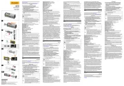
Using the Current Clamp
To use the Current Clamp, follow these instructions:
1. Connect the i200/i200s Current Clamp to the desired input on
the measuring instrument.
i200: See Figure 2.
i200s: See Figure 3. When you are using a multimeter, use the
Dual Banana to BNC Adapter (PM9081) to connect the Current
Clamp to the input.
2. i200s: On the Current Clamp, select the least sensitive range
(10 mV/A).
3. i200s: Select the appropriate clamp sensitivity on your
ScopeMeter test tool or oscilloscope.
4. Position the Current Clamp perpendicular to and centered
around the conductor.
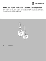
5. Make sure that the arrow marked on the clamp jaw points
toward the load for phase measurements or away from the
load (toward the source) for neutral measurements. (See
Figure 4.)
6. Observe the current value and waveform on the instrument’s
display.
7. i200s: If desired, select a lower range on the Current Clamp
and set the corresponding sensitivity (mV/A setting) on the
ScopeMeter test tool or oscilloscope.
Example with multimeters for i200:
Current Clamp sensitivity = 1 mA/A. Multimeter displays 168 mA.
168A
mA/A1
mA168
ClampCurrentysensitivit
valuedisplay
currentActual
==
=
Example with multimeters for i200s:
Current Clamp set to 10 mV/A. Multimeter displays 1.85V.
185A
mV/A10
mV1850
mV/A10
1.85V
ClampCurrentysensitivit
valuedisplay
currentActual
===
=
Figure 2. Measurement Setup for i200
V
COM
V
Ω
ST8591_190
Figure 3. Measurement Setup for i200s
Warning
If the sensitivity setting (mV/A) of the ScopeMeter test
tool or oscilloscope does not correspond with the
setting of the Current Clamp, the ScopeMeter test tool
or oscilloscope may display a much lower current
than the actual value. This may result in a false and
misleading reading and, as a consequence, incorrect
measures to be taken.
Figure 4. Orientation of the Current Clamp
Measurement Considerations
Observe the following guidelines for positioning the Current Clamp
Jaws:
• Center the conductor inside the clamp jaws.
• Make sure the clamp is perpendicular to the conductor.
• Make sure that the arrow marked on the jaw of the Current
Clamp points toward the correct direction.
Observe the following guidelines when making measurements:
• Avoid taking measurements close to other current-carrying
conductors.
• On the i200s Current Clamp, select the most appropriate range
for the current being measured to get the best accuracy.
Maintenance
Before each use, inspect the clamp. Look for cracks or missing
portions of the clamp housing and output cable insulating cover and
for loose or weakened components. Pay particular attention to the
insulation surrounding the clamp jaws. Do not use a damaged
clamp. If a clamp is damaged, tape it shut to prevent unintended
operation. A damaged clamp under warranty will be promptly
repaired or replaced (at Fluke's discretion) and returned at no
charge.
Cleaning and Storage
Periodically wipe the case with a damp cloth and detergent; do not
use abrasives or solvents. Open the jaws and wipe the magnetic
pole pieces with a lightly oiled cloth. Do not allow rust or corrosion
to form on the magnetic core ends.
If your Current Clamp does not work
If the Current Clamp does not perform properly, use the following
steps to help isolate the problem:
• Inspect the jaw mating surface for cleanliness. If any foreign
material is present, the jaws will not close properly and errors
will result.
• Verify that the function selection and range on the Multimeter,
ScopeMeter test tool or oscilloscope are correct and adjusted
to the sensitivity of the Current Clamp.
LIMITED WARRANTY & LIMITATION OF LIABILITY
This Fluke product will be free from defects in material and
workmanship for one year from the date of purchase. This warranty
does not cover fuses, disposable batteries or damage from
accident, neglect, misuse or abnormal conditions of operation or
handling. Resellers are not authorized to extend any other warranty
on Fluke’s behalf. To obtain service during the warranty period,
send your defective product to the nearest Fluke Authorized Service
Center with a description of the problem.
THIS WARRANTY IS YOUR ONLY REMEDY. NO OTHER
WARRANTIES, SUCH AS FITNESS FOR A PARTICULAR
PURPOSE, ARE EXPRESSED OR IMPLIED. FLUKE IS NOT
LIABLE FOR ANY SPECIAL, INDIRECT, INCIDENTAL OR
CONSEQUENTIAL DAMAGES OR LOSSES, ARISING FROM ANY
CAUSE OR THEORY.
Since some states or countries do not allow the exclusion or
limitation of an implied warranty or of incidental or consequential
damages, this limitation of liability may not apply to you.
Fluke Corporation Fluke Industrial B.V.
P.O. Box 9090 P.O. Box 90
Everett WA 7600 AB Almelo
98206-9090, USA The Netherlands
SERVICE CENTERS
To locate an authorized service center,
visit us on the World Wide Web:
http://www.fluke.com
or call Fluke using any of the phone numbers listed below:
+1-888-993-5853 in U.S.A. and Canada
+31-40-267-5200 in Europe
+1-425-446-5500 from other countries
Range
selector
Measurement at
a neutral
conductor
Measurement at
a phase
conductor
Product specificaties
| Merk: | Fluke |
| Categorie: | Niet gecategoriseerd |
| Model: | i200 |
| Kleur van het product: | Black, Red |
| Snoerlengte: | 1.5 m |
| Interface: | Banaanstekker |
| Aantal per verpakking: | 1 stuk(s) |
| Ondersteunde meetcategorieën: | CAT III |
Heb je hulp nodig?
Als je hulp nodig hebt met Fluke i200 stel dan hieronder een vraag en andere gebruikers zullen je antwoorden
Handleiding Niet gecategoriseerd Fluke

26 Augustus 2025
15 Juni 2025
10 Juni 2025

11 Maart 2025

7 Oktober 2024

7 Oktober 2024

7 Oktober 2024

9 September 2024

8 Juli 2024

7 December 2023
Handleiding Niet gecategoriseerd
- Control4
- MAAS
- Nils Fun
- XGIMI
- Metz
- Intellinet
- MOZOS
- Futurelight
- Luvion
- Socomec
- Briggs & Stratton
- Shimbol
- Premier
- Switel
- SpeakerCraft
Nieuwste handleidingen voor Niet gecategoriseerd
7 September 2025
5 September 2025

5 September 2025

5 September 2025

5 September 2025

5 September 2025
4 September 2025
4 September 2025
4 September 2025

4 September 2025