Fluke 90i-610s Handleiding
Fluke
Niet gecategoriseerd
90i-610s
Bekijk gratis de handleiding van Fluke 90i-610s (2 pagina’s), behorend tot de categorie Niet gecategoriseerd. Deze gids werd als nuttig beoordeeld door 59 mensen en kreeg gemiddeld 4.6 sterren uit 30 reviews. Heb je een vraag over Fluke 90i-610s of wil je andere gebruikers van dit product iets vragen? Stel een vraag
Pagina 1/2

LIMITED WARRANTY & LIMITATION OF LIABILITY
This product will be free from defects in material and workmanship for one year from the date of
purchase. This warranty does not cover damage from accident, neglect, misuse or abnormal
conditions of operation or handling. Resellers are not authorized to extend any other warranty on
behalf of the supplier. To obtain service during the warranty period, send your defective product to
the nearest Fluke Authorized Service Center with a description of the problem.
THIS WARRANTY IS YOUR ONLY REMEDY. NO OTHER WARRANTIES, SUCH AS FITNESS
FOR A PARTICULAR PURPOSE, ARE EXPRESSED OR IMPLIED. THE SUPPLIER IS NOT
LIABLE FOR ANY SPECIAL, INDIRECT, INCIDENTAL OR CONSEQUENTIAL DAMAGES OR
LOSSES, ARISING FROM ANY CAUSE OR THEORY.
Since some states or countries do not allow the exclusion or limitation of an implied warranty or of
incidental or consequential damages, this limitation of liability may not apply to you.
Fluke Corporation,
P.O. Box 9090,
Everett WA 98206-9090, U.S.A.
Fluke Industrial B.V.,
P.O. Box 90,
7600 AB, Almelo, The Netherlands.
SERVICE CENTERS
To locate an authorized service center, visit Fluke on the World Wide Web: http://www.fluke.com
or call Fluke using any of the phone numbers listed below:
+1-888-993-5853 in U.S.A. and Canada
+31-40-2675200 in Europe
+1-425-446-5500 from other countries
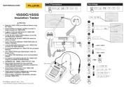
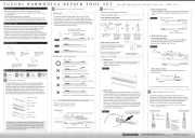
Figure 1. Installing the battery. Figure 2. Measuring Setup.
90i-610s
AC/DC Current Probe
Instruction Sheet
INTRODUCTION
The 90i-610s is a clamp-on AC/DC Current Probe designed to measure current waveforms in
automotive applications with any Test Tool capable of millivolt measurements. There are two
measurement ranges: 0 to 100 A (output voltage 10 mV/A) and 0 to 600 A (output voltage 1 mV/A).
SAFETY INFORMATION
Read First: Safety Information
To ensure safe operation and service of the Current Probe, follow these
instructions:
• Read the operating instructions before use and follow all safety instructions.
• Use the Current Probe only as specified in the operating instructions; otherwise the
current probe’s safety features may not protect you.
• Check the magnetic mating surfaces of the probe jaws; these should be free of dust,
dirt, rust, and other foreign matter.
• Adhere to local and national safety codes. Individual protective equipment must be
used to prevent shock and arc blast injury where hazardous live conductors are
exposed.
• Do not hold the Current Probe anywhere beyond the tactile indicator, see Figure 2.
• Before each use, inspect the Current Probe. Look for cracks or missing portions of the
Current Probe housing or output cable insulation. Also look for loose or weakened
components. Pay particular attention to the insulation surrounding the jaws.
• Never use the Current Probe on a circuit with voltages higher than 600 V CAT II or 300
V CAT III.
− CAT II equipment is designed to protect against transients in circuits directly
connected to the low-voltage installation, such as household appliances, portable
tools and similar equipment.
− CAT III equipment is designed to protect against transients in equipment in fixed
equipment installations, such as distribution panels, feeders and short branch
circuits, and lighting systems in large buildings.
• Use extreme caution when working around bare conductors or bus bars. Contact with
the conductor could result in electric shock.
• Use caution when working with voltages above 60 V dc, 30 V ac rms or 42 V ac peak.
Such voltages pose a shock hazard.
• Keep cables away from rotating parts or belts.
Tactile indicator
March 2002 , rev 1, 10/05 GB
© 2002-2005 Fluke Corporation. All rights reserved.
Printed in The Netherlands.
All product names are trademarks of their respective
companies.

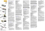
SYMBOLS
May be used on HAZARDOUS LIVE conductors.
Product is protected by double insulation.
Risk of Danger. Important information. See Users Manual.
Risk of Electric Shock.
Complies with relevant European standards.
Earth ground
Battery
UNPACKING
The following items should be included in the box of your Current Probe:
• AC/DC Current Probe 90i-610s
• Instruction sheet (This document)
• 9V Battery, Type IEC 6LR61
• BNC-to-Banana Adapter PM9081/001
Check the contents of the shipping box for completeness. If something in the box has been
damaged or is missing, contact your distributor immediately.
INSTALLING THE BATTERY
WARNING
To avoid electrical shock, unclamp the Current Probe from any conductor, and
disconnect the Probe’s BNC connector from the Test Tool or any other
measurement tool before installing or replacing the battery.
Refer to Figure 1 and proceed as follows:
• Put the Current Probe in the OFF position.
• The battery cover is present in the bottom side of the Probe body. Loosen the screw in the
battery cover with a small crossheaded screwdriver.
• Slide the battery cover away from the Current Probe.
• Install the 9V battery (IEC 6LR61). Arrange the battery leads so that they will not be pinched
between Probe body and the battery cover.
• Reinstall the battery cover and secure the screw.
SPECIFICATIONS
All Electrical Specifications are valid at a temperature of 23
°
C
±
5
°
C (73
°
F
±
9
°
F).
Current Ranges: 0 to 100 A DC or AC peak, 0 to 600 A DC or AC peak.
Output Signals: 100 A range: 10 mV/A / 600 A range: 1 mV/A
Measurement Category Ratings:
300 V CAT III & 600 V CAT II, pollution degree 2 per EN 61010-1 & EN 61010-02-032.
Complies with American industry standards UL61010B-1 & UL61010B-2-032, and European
standards EN/IEC 61010-1 2 nd Edition & EN/IEC 61010-02-032.
Accuracy:
Error (after zero check) Input Current Error
(DC or AC peak) 10 mV/A 1 mV/A
0 to 100 A
100 to 400 A
400 to 600 A
± ±2 % of reading 1 A
--
--
±3.5 % of reading ±3 A
±2.0 % of reading ±2 A
±3.0 % of reading ±2 A
Maximum Nondestructive Current: 800 A peak
Input Load Impedance (of host instrument): >1 MΩ in parallel with up to 100 pF
Useful Bandwidth: DC and 40 to 400 Hz.
Dimensions: 73 x 215 x 27 mm (2.9 x 8.4 x 1.1 inches)
Weight: 400 g (14 oz.), battery included
Temperature: operating: 0 to 50 ° ° °C (32 to 122 F), max humidity 75%; nonoperating: -20 to 60 C
(-4 to 140 °F), max humidity 80%
Altitude: operating: 0 to 2000 meters (0 to 6500 feet); nonoperating: 0 to 12000 meters (0 to 40000
feet)
Temperature Coefficient:
0.2 * accuracy/ °C max. for temperature T<18 °C and T>28 °C (T<64 °F and T>82 °F)
Battery Life: With Alkaline IEC 6LR61, 60 hours typical, 40 hours minimum.
POWER AND DEMAGNETIZING
During normal operation the green ON-indicator flashes; the red LOW-indicator is on when battery
voltage is low.
WARNING
To avoid false readings which could cause injury, replace battery as soon as the
red Low Battery Indicator LED lights.
Auto power off automatically switches the Probe off after 30 minutes.
To Demagnetize the Probe, open and close the jaws several times.
CLEANING AND STORAGE
Periodically wipe the case with a damp cloth and detergent; do not use abrasives or solvents. Open
the jaws and wipe the magnetic pole pieces with a lightly oiled cloth. Do not allow rust or corrosion to
form on the magnetic core ends. Remove the battery if the Probe is not used for periods of longer
than 60 days.
MEASUREMENT INSTRUCTIONS
Refer to Figure 2 and proceed as follows:
• Connect the Current Probe to Input A or the volts and COM inputs of the Test Tool.
If necessary use the PM9081 adapter that is supplied with the Probe: for correct polarity, the
red leg of the adapter must be inserted into Input A or volts input and the black into COM.
• On the Current Probe: select range. Ensure that the green ON-indicator flashes; the red
LOW-indicator must be off.
• Adjust the Test Tool to current readout at a sensitivity of 10 mV/A or 1 mV/A and current AC +
DC measurement. For the proper settings see the user documentation of the Test Tool.
• Zero the Probe, especially after you have selected another measurement range.
• Clamp the Current Probe around the conductor. The + and – indications marked on the jaw of
the Probe must correspond with the orientation of the current to be measured. This assures a
correct reading of the current flow.
• Observe the current value and the shape of the waveform on the display of the Test Tool.
Product specificaties
| Merk: | Fluke |
| Categorie: | Niet gecategoriseerd |
| Model: | 90i-610s |
Heb je hulp nodig?
Als je hulp nodig hebt met Fluke 90i-610s stel dan hieronder een vraag en andere gebruikers zullen je antwoorden
Handleiding Niet gecategoriseerd Fluke

26 Augustus 2025
15 Juni 2025
10 Juni 2025

11 Maart 2025

7 Oktober 2024

7 Oktober 2024

7 Oktober 2024

9 September 2024

8 Juli 2024

7 December 2023
Handleiding Niet gecategoriseerd
- Dahua Technology
- Steinberg
- Metapen
- ZeeVee
- Swingline GBC
- Gami
- Exelpet
- SunBriteTV
- Truelife
- Dynon Avionics
- VariZoom
- Handicare
- Dunlop
- Mophie
- Power Acoustik
Nieuwste handleidingen voor Niet gecategoriseerd
7 September 2025
5 September 2025

5 September 2025

5 September 2025

5 September 2025
5 September 2025
4 September 2025
4 September 2025
4 September 2025

4 September 2025