Festo CTEU-CC Handleiding
Festo Niet gecategoriseerd CTEU-CC
Bekijk gratis de handleiding van Festo CTEU-CC (4 pagina’s), behorend tot de categorie Niet gecategoriseerd. Deze gids werd als nuttig beoordeeld door 16 mensen en kreeg gemiddeld 4.1 sterren uit 9 reviews. Heb je een vraag over Festo CTEU-CC of wil je andere gebruikers van dit product iets vragen? Stel een vraag
Pagina 1/4
1Installation
1.1Allgemeines
DieseBeschreibungenthältInformationenzurMontage
desBusknotensaufeinemgeeignetemGerät(z.B.
Ventilinsel)vonFestomitI-Port-SchnittstelleundzurIn-
stallationdieserKombinationineinemübergeordneten
Steuerungssystem.
Hinweis
..................................................
–CC-Link
®
,TORX
®
sindeingetrageneMarkenderje-
weiligenMarkeninhaberinbestimmtenLändern.
1.2AllgemeineHinweise
DerindieserBeschreibungdokumentierteBusknoten
CTEU-CCistausschließlichfürdenEinsatzalsTeilnehmer/
Station(Slave)amFeldbusCC-Linkbestimmt.Erdarfnurim
OriginalzustandohneeigenmächtigeVeränderungenund
nurintechnischeinwandfreiemZustandeingesetztwerden.
DerBusknotenistfürdenEinsatzimIndustriebereich
vorgesehen.ImWohnbereichmüssenevtl.Maßnahmen
zurFunkentstörunggetroffenwerden.
ZielgruppedieserBeschreibungsindausgebildeteFach-
leutederSteuerungs-undAutomatisierungstechnik,die
ErfahrungenbeiderInstallationvonTeilnehmernamFeld-
busCC-Linkhaben.
Warnung
.................................................
VerletzungsgefahrdurchunkontrollierteBewegungen
angeschlossenerGeräte.
StellenSiesicher,dasssichElektrikundPneumatikin
strom-unddrucklosemZustandbefinden.
VorArbeitenanderPneumatik:
•Druckluftversorgungausschalten
•Ventilinselentlüften
VorArbeitenanderElektrik,z.B.vorInstallations-oder
Instandhaltungsarbeiten:
•Spannungsversorgungenausschalten
Sievermeidendamit:
–unkontrollierbareBewegungenlosgelösterSchlauch-
leitungen
–ungewollteundunkontrollierteBewegungenderan-
geschlossenenAktorik
–undefinierteSchaltzuständederElektronik
Hinweis
..................................................
DerBusknotenenthältelektrostatischgefährdeteBau-
elemente.
•BerührenSiekeineelektrischen/elektronischenBau-
elemente.
•BeachtenSiedieHandhabungsvorschriftenfürelek-
trostatischgefährdeteBauelemente.
SievermeidendamiteinZerstörenderElektronik.
Hinweis
..................................................
VerwendenSieeinenFestoFeldbussteckerfürdenAn-
schlussandenFeldbussowieSchutzkappenbzw.
Blindstopfen,umungenutzteAnschlüssezuverschlie-
ßen.SoerreichenSiedieSchutzartIP65/67.
1.3Montage
Hinweis
..................................................
InformationenzurMontagedesBusknotensaufder
dezentralenElektrik-Anschlussplatte,TypCAPC-...,fin-
denSieinderMontageanleitung,diederAnschluss-
plattebeiliegt.
ZurMontagedesBusknotensisteineVentilinselvonFesto
mitI-Port-Schnittstelleerforderlich.
1.PrüfenSiedieDichtungenundDichtflächenanBus-
knotenundVentilinsel.
2.SteckenSiedenBusknotenlagerichtigundohnezu
verkantenaufdieVentilinsel.
3.DrehenSiediedreiselbstschneidendenSchraubenzu-
nächstmiteinemTORX-Schraubendreher(GrößeT10)
leichtein.NutzenSieggf.vorhandeneGewindegänge.
4.DrehenSiedieSchraubenmit1,0Nmfest.
Busknoten,TypCTEU-CC..........................
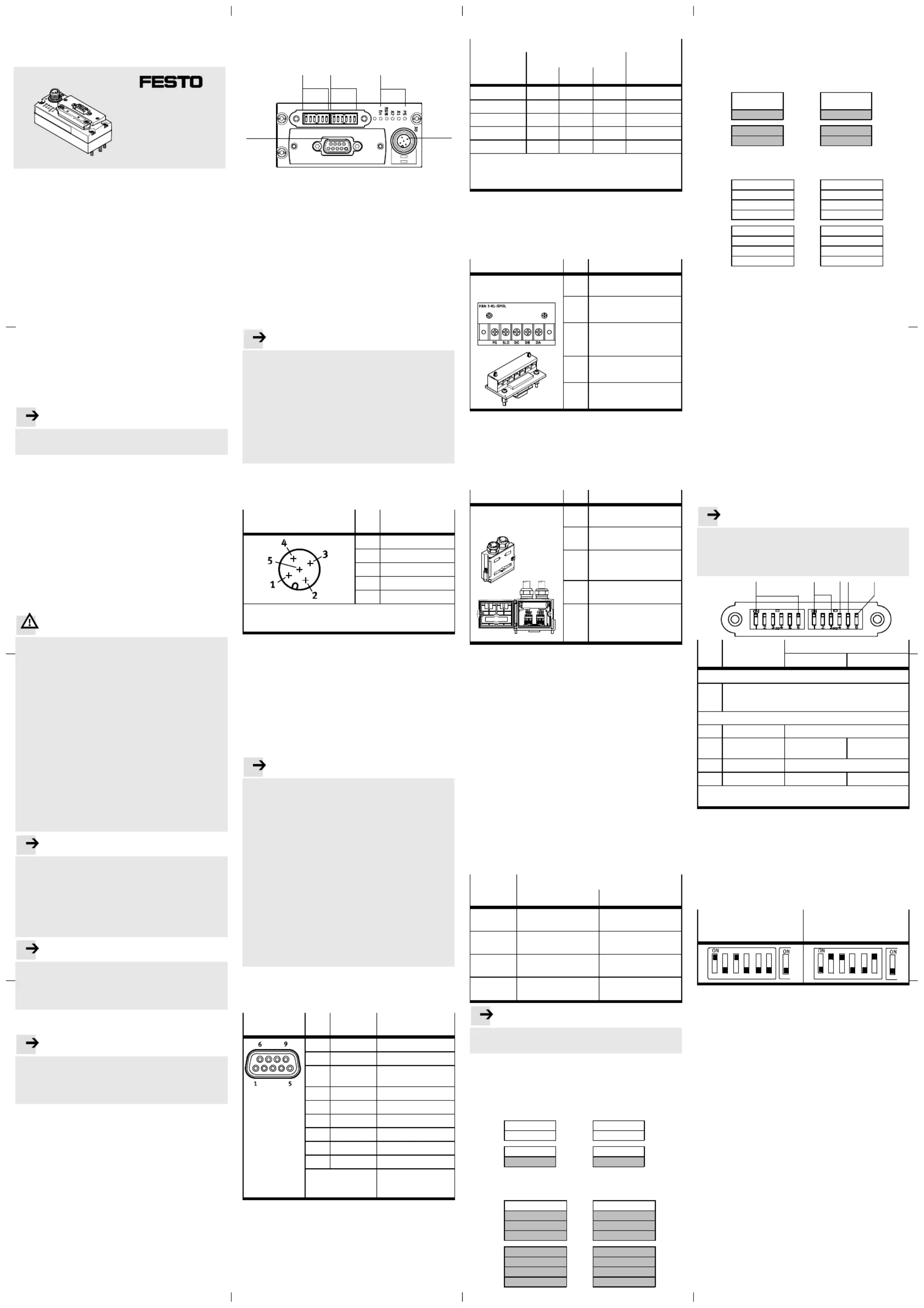
2Anschluss-undAnzeigeelemente
AufdemBusknotenfindenSiefolgendeelektrischeAn-
schluss-undAnzeigeelemente:
123
4
5
1
DIL-Schaltergruppe1(Kap.5.4)
2DIL-Schaltergruppe2(Kap.5.4)
3Status-LEDs
(ZustandsanzeigeundDiagnoseKap.6)
4SpannungsversorgungfürBusknotenundggf.ange-
schlosseneDevices(z.B.Ventilinsel)(Kap.3)
5Feldbusanschluss(D-Sub-Stecker,Kap.4)
3Spannungsversorgung
DerBusknotenverfügtübergetrennteSignal-undLast-
spannungsversorgungen.Erversorgtauchdieüberdie
I-Port-SchnittstelleangeschlossenenGeräte(Devices)mit
Spannung.
Hinweis
..................................................
•VerwendenSiefürdieelektrischeVersorgungaus-
schließlichPELV-StromkreisenachEN60204-1(Pro-
tectiveExtra-LowVoltage,PELV).BerücksichtigenSie
zusätzlichdieallgemeinenAnforderungenanPELV-
StromkreisegemäßderEN60204-1.
•VerwendenSieausschließlichStromquellen,dieeine
sichereelektrischeTrennungderBetriebsspannung
nachEN60204-1gewährleisten.
•SchließenSiedieStromkreisefürSignal-undLast-
spannungsversorgunggrundsätzlichbeidean.
DurchdieVerwendungvonPELV-Stromkreisenwirdder
SchutzgegenelektrischenSchlag(Schutzgegendirektes
undindirektesBerühren)nachEN60204-1sichergestellt.
Spannungsversorgungs-
anschluss(M12,A-codiert)
PinBelegung
124VPS(Elektronik)
224VPL(Last)
30VPS(Elektronik)
40VPL(Last)
5FE
1)
1)AnschlussanFunktionserdemussüberdasangeschlosseneGerät
bzw.dieElektrik-Anschlussplatte(TypCAPC-…)sichergestellt
werden.
VerwendenSiezumAnschlussanNetzteilebzw.
SpannungsversorgungenKabelmitM12-Buchse,A-co-
diert,EN61076-2-101(Zubehörwww.festo.com/
catalogue).
Die“PS”-LEDleuchtetgrün,wenndieSpannungsversor-
gunganbeidenStromkreisenkorrektanliegt.DieLEDX1
bzw.X2leuchtetgrün,wenneinDeviceangeschlossenist
(Kap.6).
4AnschließendesFeldbusses
Hinweis
..................................................
BeifehlerhafterInstallationundhohenÜbertragungs-
ratenkönnenDatenübertragungsfehlerdurchSignal-
reflexionenundSignaldämpfungenauftreten.
•VerwendenSiegrundsätzlichanbeidenEndendes
FeldbusseseinenAbschlusswiderstand(110Ω,
0,5W)entsprechendderCC-Link-Spezifikation.
•BeachtenSiedieSpezifikationenIhresübergeordne-
tenSteuerungssystemsbezüglichKabeltyp,verwend-
barerT-Adapterundmax.LängederStichleitungen
bzwAbzweigungen.
•VerbindenSiedieSchirmungdurchgehendanallen
FeldbuskabelnunderdenSiedieSchirmunganje-
demGerät.
•BerücksichtigenSiebeiderBerechnungdermax.
zulässigenLängedesFeldbuskabelsabhängigvon
dergenutztenBaudrateauchdieSummederLänge
derStichleitungenundAbzweigungen.
D-Sub-SteckeramBusknoten
FürdasAnschließendesBusknotensandenFeldbusbe-
findetsichaufdemBusknoteneine9-poligeD-Sub-Buchse.
D-Sub-Buchse
PinSignalan-
schluss
Beschreibung
1n.c.nichtangeschlossen
2DADataA
3DGDataGround
(Datenbezugspotential)
4n.c.nichtangeschlossen
5n.c.nichtangeschlossen
6n.c.nichtangeschlossen
7DBDataB
8n.c.nichtangeschlossen
9n.c.nichtangeschlossen
Gehäuse
Kabelschirmung,Ver-
bindungzurFunktions-
erdeFE
Feldbuskabel/-leitung
FürdieFeldbuskommunikationempfiehltFestodie
VerwendungverdrillterundgeschirmterLeitungen.
•VerwendenSiemindestenseinegeschirmte3-Draht-
leitungnachCC-Link-Spezifikation.
•SchließenSiedieSchirmungdesFeldbuskabelsam
Feldbussteckeran.
...............................................
Baudraten
Einstellbare
Baudrate
[kBd]
DIL-Schalter-Stellung
1)
Max.
Leitungs-
länge
2)
[m]
789
1561200OFFOFFOFF
625900ONOFFOFF
2500OFFONOFF400
5000160ONONOFF
10000(default)100OFFOFFON
1)
EinstellenderDIL-Schalter(sieheKap.5.4).Nichtdargestellte
Schalterstellungs-Kombinationensindunzulässig!
2)
GesamtlängeallerLeitungeneinschließlichStichleitungenund
Abzweigungen(ohneEinsatzvonRepeatern)
FeldbusanschlussvonFesto
ZumeinfachenAnschlussdesFeldbusknotenskannein
FeldbusanschlussmitKlemmleistevonFesto(Typ
FBA-1-KL-5POL)verwendetwerden.ErreichbareSchutz-
klasse:IP20.
Anschluss-Block
PinBelegung
Anschluss-Block
TypFBA-1-KL-5POL
FGFunktionserde
SLDKabelschirm
DGDataGround
(Datenbezugspotential)
DBDataB
DADataA
FeldbussteckervonFesto
MiteinemFeldbussteckervonFesto(TypFBS-SUB-9-GS-
2x4POL-B)kannderBusknotenvomFeldbusgetrennt
werden,ohnedieKommunikationderanderenGeräteim
Feldbuszuunterbrechen.ErreichbareSchutzklasse:
IP65/67(beiVerschlussallerAnschlüsse).
Feldbusstecker
PinBelegung
Feldbusstecker
TypFBS-SUB-9-GS-2X4POL-B
DADataA
DBDataB
DGDataGround
(Datenbezugspotential)
*NC*nichtangeschlossen
FEÜberdenKlemmbügelmit
demGehäusedesD-Sub-
Steckersverbunden
5Inbetriebnahme
5.1Adressierung
DieAdressierungkannwahlweiseimBit-oderimWortbe-
reicherfolgen.DieAnzahlderbelegtenStationenwird
vomFeldbusknotenautomatischermittelt.
–ImBit-Bereichentspricht1Stationjeweils32BitEin-
gangs-undAusgangsadressen.
–ImWort-Bereichentspricht1Stationjeweils4Wörtern
(1Wort=2Byte)Eingangs-undAusgangsadressen.
–Indenersten2Eingangs-Bytesdesnichtverwendeten
BereichsstehtdasDiagnosewort(soferndieDiagnose
aktiviertist).
–DurchSetzenvonBit0deserstenAusgangs-Bytesim
ungenutztenBereichkanndieDiagnose-Funktionak-
tiviertbzw.deaktiviertwerden.
–Diejeweilsletztes2BytesdesBit-Bereichssind
reserviert.Bit11desEingangsbereichsenthältdas„Re-
moteReady“-Bit(RR).DasBithatbeifunktionierender
KommunikationmitdemFeldbusdenWert„1“.
DarausergebensichfolgendeZuordnungen:
Benötigte
Stationen
VerfügbareE/Asim
Bit-BereichWort-Bereich
1StationBiszu16E/As
(1…2Byte)
Biszu64E/As
(1…8Byte)
2StationenBiszu48E/As
(3…6Byte)
Biszu128E/As
(9…16Byte)
3StationenBiszu80E/As
(7…10Byte)
–
4StationenBiszu112E/As
(11…14Byte)
–
Hinweis
..................................................
Beimehrals112E/AswirdautomatischderWort-Be-
reichverwendet.
Beispiel:
Aufteilungvon2Stationen,AdressierungimBit-Bereich.
Bit-Bereich
Eingänge(RX)Ausgänge(RY)
Station1E15…E0
Byte1…0Byte1…0A15…A0
E31…E16Byte3…2Byte3…2A31…A16
Station2E47…E32Byte5…4Byte5…4A47…A32
Bit11=RRByte7…6–reserviert–Byte7…6
Wort-Bereich
Eingänge(RWr)Ausgänge(RWw)
Station1Diagnose-Wort
Wort0Wort0Bit0=Diag.on/off
–reserviert––reserviert–Wort1Wort1
–reserviert––reserviert–Wort2Wort2
–reserviert––reserviert–Wort3Wort3
Station2–reserviert––reserviert–Wort4Wort4
–reserviert––reserviert–Wort5Wort5
–reserviert––reserviert–Wort6Wort6
–reserviert––reserviert–Wort7Wort7
de.............................................
Beispiel:
Aufteilungvon2Stationen,AdressierungimWort-Bereich.
Bit-Bereich
Eingänge(RX)Ausgänge(RY)
Station1Diagnose-Wort
Byte1…0Bit0=Diag.
on/off
Byte1…0
–reserviert––reserviert–Byte3…2Byte3…2
Station2–reserviert––reserviert–Byte5…4Byte5…4
Bit11=RRByte7…6Byte7…6–reserviert–
Wort-Bereich
Eingänge(RWr)Ausgänge(RWw)
Station1E15…E0
Wort0Wort0A15…A0
E31…E16Wort1Wort1A31…A16
E47…E32Wort2Wort2A47…A32
E63…E48Wort3Wort3A63…A48
Station2E79…E64Wort4Wort4A79…A64
E95…E80Wort5Wort5A95…A80
E111…E96Wort6Wort6A111…A96
E127…E112Wort7Wort7A127…A112
5.2Failstate
FailstateregeltdasVerhaltendesBusknotensundder
angeschlossenenDevicesbeiKommunikationsfehlern.
–Holdlastestate
BeieinemFehlerinderKommunikationbleibtderletzte
Statuserhalten.
–Reset(default)
BeieinemFehlerinderKommunikationwirdderStatus
zurückgesetzt.
5.3DemontierenderDIL-Schalter-Abdeckung
ZumEinstellendesBusknotensmussdieAbdeckungder
DIL-Schalterdemontiertwerden:
1.SchaltenSiedieSpannungsversorgungaus.
2.DrehenSiediebeidenBefestigungsschraubender
transparentenAbdeckungherausundentfernenSiedie
Abdeckung.
5.4EinstellenderDIL-Schalter
MitdenDIL-SchalternstellenSiediefolgendenParameter
fürdenBusknotenein.
Hinweis
..................................................
DieDIL-SchalterwerdennurbeimStartdesBus-
knotensbzw.desDevicesabgefragt.Anschließende
VeränderungenderSchalterstellungenwerdenerst
beimnächstenStartberücksichtigt.
1
2
45
3
Pos.DIL-Schalter
1)
Funktion
ONOFF
DIL-Schaltergruppe1:
11...6:Stationsnummer(1…64),binärcodiert(Adresseist
dereingestellteBinärwert+1,„0“istnichteinstellbar)
Default:Stationsnummer1(Schalter1…6„OFF“)
DIL-Schaltergruppe2:
27…9:BaudrateFeldbuskabel/-leitung
310:Adressierungs-
bereich
WortbereichBit-Bereich
(default)
411reserviert
512:FailstateHoldlaststateReset(default)
1)Schalterstellung“ON”=EIN(Schalterstehtoben)
Schalterstellung“OFF”=AUS(Schalterstehtunten)
GehenSiefolgendermaßenvor:
1.WeisenSiedemBusknoteneinenochnichtbelegteSta-
tionsnummerzu.
2.StellenSiedieBaudrateein.
3.StellenSiedenFailstate-Modusein.
Die“RUN”-LEDleuchtetgrünbeifehlerfreierKommunika-
tionzurSPS(Kap.6).
BeispieleeingestellterStationsnummern(Binärwert+1)
EingestellterBinärwert5,
entsprichtStations-
nummer:06(5+1)
EingestellterBinärwer38,
entsprichtStations-
nummer:39(38+1)
123456
1
123456
1
5.5MontierenderDIL-Schalter-Abdeckung
1.SetzenSiedieAbdeckungvorsichtigaufdenBus-
knoten.AchtenSieaufdiekorrekteLagederDichtung!
2.DrehenSiediebeidenBefestigungsschraubenerst
handfestunddannmitmax.0,4Nmfest.
Uni
v
ersellerBusknoten
CTEU-CC
Beschreibung
Busknoten,TypCTEU-CC
FeldbusprotokollCC-Link
Original:de
CTEU-CC-D2
8004836
Festo SE& Co. KG
Postfach
D-73726Esslingen
+49/711/347-0
www.festo.com
de1206NH
Product specificaties
| Merk: | Festo |
| Categorie: | Niet gecategoriseerd |
| Model: | CTEU-CC |
Heb je hulp nodig?
Als je hulp nodig hebt met Festo CTEU-CC stel dan hieronder een vraag en andere gebruikers zullen je antwoorden
Handleiding Niet gecategoriseerd Festo

3 Mei 2026
30 April 2026
29 April 2026
29 April 2026
29 April 2026
29 April 2026
28 April 2026
28 April 2026
28 April 2026
28 April 2026
Handleiding Niet gecategoriseerd
Nieuwste handleidingen voor Niet gecategoriseerd
24 Juli 2026
24 Juli 2026
23 Juli 2026
23 Juli 2026
23 Juli 2026
23 Juli 2026
23 Juli 2026
23 Juli 2026
23 Juli 2026
23 Juli 2026