Electronics International FP-5L-60 Handleiding


Lees hieronder de 📖 handleiding in het Nederlandse voor Electronics International FP-5L-60 (22 pagina's) in de categorie Niet gecategoriseerd. Deze handleiding was nuttig voor 18 personen en werd door 2 gebruikers gemiddeld met 4.5 sterren beoordeeld

Pagina 1/22
II 0506931
5/6/93
Rev. I: 7/2/02
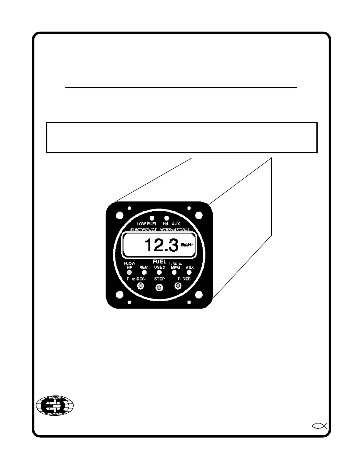
Installation Instructions
(FP-5 and FP-5L)
Fuel Flow/Pressure
2.5"
2.5"
3.65"
Electronics International Inc. ®
63296 Powell Butte Hwy • Bend, OR 97701 • (541) 318-6060 • www.Buy-EI.com
Unit Model:__________________
Flow Transducer Model:__________________
S/N:_____________________
You must read this manual before installing or operating the instrument. This
manual contains warranty and other information that may affect your decision
to install this product and/or the safety of your aircraft.
Important Notice
***** MUST READ *****
If you think it is not important to read this manual, you're wrong! This manual
contains important installation information that may affect the safety of your air-
craft, delay your installation or affect the operation of your instrument. You Must
read this manual prior to installing your instrument. Any deviation from these
installation instructions is the sole responsibility of the installer/pilot and may
render the STC invalid.
Read the Warranty / Agreement. There is information in the Warranty / Agreement that may alter
your decision to install this product. If you do not accept the terms of the Warranty / Agreement, do not
install this product. This product may be returned for a refund. Contact Electronics International inc. for
details.
A gravity feed fuel system or any engine rated over 300 H.P. must use an FT-90 flow trans-
ducer. An engine rated over 550 H.P. must use the FT-180 flow transducer. The standard Fuel
Transducer (FT-60) shipped with the FP-5 or FP-5L Fuel Flow/Pressure instrument is intended to
be used on aircraft equipped with fuel pumps with engines rated below 300 H.P.
Transducer Identification Markings: There are two suppliers of the FT-60 and FT-90 Flow
Transducer (E.I. inc and Flowscan). The E.I. units are equipped with a PMA label.
FT-60 - The Flowscan unit is marked "201" on the top of the unit.
FT-90 - The Flowscan unit is marked "231" on the top of the unit.
FT-180 - Equipped with a 3/4 - 16 male fitting.
On a gravity feed system the fuel pressures are lower than the FP-5 or FP-5L can measure.
Therefore, disable the Fuel Pressure feature on the FP-5 or FP-5L when used on a gravity feed
system.
If your aircraft is not covered on our STC (found at the back of this manual), you must
perform the flow and pressure tests in FAA document A.C. 23.955-1 (Substantiating Flow Rates
and Pressures in Fuel Systems of Small Airplanes) to insure safe and proper operation.
Installation of the FP-5 on an aircraft with a fuel return line from the Pressure Carburetor requires
a FFDM-1 Differential Module (see price sheet).
The placard "Do Not Rely on Fuel Flow Instrument to Determine Fuel Levels in Tanks" must be
mounted on the aircraft instrument panel near the FP-5.
If the aircraft is equipped with a primary fuel flow and/or pressure instrument, the following
placard must be mounted on the aircraft instrument panel near the FP-5: "Refer to Original Fuel Flow/
Pressure Instrumentation for Primary Information".
Contents
Warranty ................................................................................................... 2
1. Important Information and Initial Check Out: .................................... 3
2. Install the Fuel Flow Transducer: ....................................................... 4
3. Install A Functional Module: ............................................................... 5
4. Install the Circular Connector: ........................................................... 5
5. Route the Power and Ground Wires: .................................................. 6
6. Route the Backlight Wires: ................................................................. 6
7. Route the (Optional) External Warning Control Line: ........................ 6
8. Route the Fuel Flow Transducer Wires: ............................................. 6
9. Install A Functional Module: ............................................................... 7
10. (FP-5L Only) Connect the RS-232/422 Input Lines: ......................... 7
11. (FP-5L Only) Connect the RS-232 Output Line: ................................ 8
12. Install the Fuel Flow Differentail Module (FFDM-1) .......................... 8
13. Install the Instrument in the Panel: ................................................... 9
14. Connect the Circular Connector to the Instrument: ......................... 9
15. System Check-out: ............................................................................. 9
16. Initial Programming: ........................................................................... 10
Wiring Diagrams ....................................................................................... 11
Circular Connectors ................................................................................. 13
Specifications and Operating Features ................................................... 15
Fuel Flow Transducer Installation Drawings: ...................................... 17-20
STC Information ...................................................................................... Appendix
1


Product specificaties

Merk: Electronics International
Categorie: Niet gecategoriseerd
Model: FP-5L-60

Heb je hulp nodig?

Als je hulp nodig hebt met Electronics International FP-5L-60 stel dan hieronder een vraag en andere gebruikers zullen je antwoorden


Handleiding Niet gecategoriseerd Electronics International

Handleiding Niet gecategoriseerd

Nieuwste handleidingen voor Niet gecategoriseerd