DataComm 50-6653-WH-KIT Handleiding
DataComm
Niet gecategoriseerd
50-6653-WH-KIT
Bekijk gratis de handleiding van DataComm 50-6653-WH-KIT (5 pagina’s), behorend tot de categorie Niet gecategoriseerd. Deze gids werd als nuttig beoordeeld door 25 mensen en kreeg gemiddeld 4.7 sterren uit 13 reviews. Heb je een vraag over DataComm 50-6653-WH-KIT of wil je andere gebruikers van dit product iets vragen? Stel een vraag
Pagina 1/5

WARNING
DataComm Electronics’ products shall be installed and used ly as indicated in DataComm Electronics’ product instruction sheets. on
Instruction sheets are available online at w.datacommelectronics.com. ww
CAUTION
For shock protection, this dev e must be pr erly grounded.ic op
Use copper wire only with this device.
IMPORTA INSTRUCTIONS NT
Read and understand all instructions.
Follow all warnings and instructions marked on the product.
Do not use this product near water, for example near a bath tub, wash bowl, kitchen sink, la dry tub, in a wet basement, or near aun
sw p .imming ool
SA VE THESE INSTRUCTIONS.
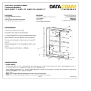
Instruction / Installation Sheet
Recessed TV Cable & Media
Organizer Kit with Duplex Power
Part # 50-6653-WH-KIT
DataComm Electronics, Inc.
6349 Peachtree Street
Norcross, GA 30071-1725
888.223.7977
770.662.8205
www.DataCommElectronics.com
Parts Included:
• Recessed Media Box II (Top Plate)
• Old Work Electrical Box with four (4) Mounting Screws
• 15 Amp/125 Volt Tamper Resistant Duplex Receptacle
• Flexible Pass-Through Accessory Plate
• Six (6) Port Keystone Accesory Plate
• Blank Accessory Plate
• Bottom Plate w/ Easy Push-In Connectors
• 8 ft. Extension Cord with 360 Rotating Flat Head˚
Tools Required:
• Drill with Phillips Bit or Phillips Head Screw Driver
• Pen or Pencil
• Sheetrock Saw or Utility Knife
• 6 Ft. Tape Measure
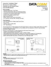
Use the Recessed TV Cable Organizer Kit with Duplex Power to install low voltage cables behind your HDTV
or other display device. The Media Box can be installed with the receptacle on the left or right side (see
Installation Diagram below).
Features of the Recessed TV Cable Organizer Kit with Duplex Power include:
• Compact size fits behind small and large TV’s
• Snap-in side plate features cutouts for 1” and 2” conduit or tubing
• HDTV/display device plug recesses completely into the wall when plugged into the Media Box
• Flexible Pass-Through Accessory Plate conceals low voltage pass-through opening
• Bottom plate features easy-snap in connectors for a fast and easy install
Page 1 of 5
11/16/16
Installation Diagram
Front View
Installation Diagram
Back View
Concealed Wiring
(hidden in wall)
Flat Screen TV
Flat Screen TV
Concealed Wiring
(hidden in wall)
Receiver
Receptacle
Receiver
Receptacle

2Fig.
Fig. 3
Fig. 1
Fig. 4
Fig. 6
Installation Instructions:
Figure 1:
Cut out the supplied templates for the top and bottom plates from pages 4 & 5 of this
instruction sheet. Place the templates on the wall in the desired install location. Note: the
top plate will install high on the wall in the location where you will hang your TV. The
bottom plate installs directly below the top plate near the floor.
Using your pen or pencil, trace the templates on the wall. Then use a drywall saw or utility
knife to cut holes in the drywall the size of the templates.
Figure 2:
Take the pre-wired electrical box and run the electrical building wire into the wall.
Figure 3:
Use the four provided screws to secure the Old Work Electrical Box and Receptacle to
the mounting studs on the backside of the Top Plate.
Figure 4:
Important: Before installing the Top Plate into the template opening, make sure to pull
your low voltage cables through the low voltage cable opening.
After low voltage pass through: Starting with the receptacle side of the Top Plate
slowly sliding it into the opening. Swing the opposite side of the plate into position until the
entire box is flush with the wall. Now screw down the screws with wings; these wings
fasten tightly against the back of the drywall.
Figure 6:
The top plate is now installed. You can now install your TV wall mount and hang your flat
panel display.
Page 2 of 5
888.223.7977
770.662.8205
www.DataCommElectronics.com
Instruction / Installation Sheet
Recessed TV Cable & Media
Organizer Kit with Duplex Power
Part # 50-6653-WH-KIT CONTINUED
11/16/16
Fig. 5
Figure 5:
Before installing the Top Plate into the wall opening, make sure to pull your low voltage
cables through the top and bottom openings or the side opening.
If you are using flexible tubing, cut out either the 1” or 2” knockout (depending on your
flexible tube hole size) from the snap-in cover plate, now run your cables through the
snap-in plate opening, then attach your flexible.

Instruction / Installation Sheet
Recessed TV Cable & Media
Organizer Kit with Duplex Power
Part # 50-6653-WH-KIT CONTINUED
888.223.7977
770.662.8205
www.DataCommElectronics.com
Fig 7
Fig 8
Fig 9
Fig 10
Figure 8:
Insert the stripped end of the wires into the push-in connectors. First, insert the stripped
black wire into the open side of the push-in connector with the black wire – be sure to
push the stripped black wire completely into the connector. Now insert the stripped white
wire into the open side of the push-in connector with the white wire. Next, insert the bare
copper ground wire into the open side of the push-in connector with the green ground
wire.
Figure 7:
Now that you have pulled the top power outlet plate’s electrical building wire though the
bottom hole, bend the wire straight. Push the stripped end of the wire through the
opening in the white old work box.
Figure 9:
Place all of the wires and the push-in connectors into the white old work box.
Figure 10:
Now screw the white old work box to the back of the bottom plate.
Figure 11:
Pull your low voltage cables through the cable opening in the bottom plate.
Stop: Important: Before installing the bottom recessed plate with inlet into the bottom
template opening, make sure to pull your low voltage cables through the low voltage cable
opening in the back of the plate. After you have pulled your low voltage and audio/video
cables through the bottom power input plate, insert the side of the plate with the electrical
work box into the wall. (see Figure 11). Swing the right side of the plate into position until
the entire plate is flush against the wall. Now tighten the screws with wings. These wings
fasten tightly against the back of the wall. Note: Do not overtighten screws.
Figure 12:
Plug your power cord set into the bottom power input plate. Complete installation by
plugging the male end of the power cord set into the nearby wall receptacle.
Fig 11
Fig 12
Page 3 of 5
11/16/16
Product specificaties
| Merk: | DataComm |
| Categorie: | Niet gecategoriseerd |
| Model: | 50-6653-WH-KIT |
Heb je hulp nodig?
Als je hulp nodig hebt met DataComm 50-6653-WH-KIT stel dan hieronder een vraag en andere gebruikers zullen je antwoorden
Handleiding Niet gecategoriseerd DataComm
4 Augustus 2025
4 Juli 2025

15 Juni 2023
Handleiding Niet gecategoriseerd
- DoughXpress
- Nuna
- Nite Ize
- TacTic
- Everpure
- Vello
- Hansa
- Trelock
- Digitech
- Viatek
- Orbitrek
- Focus Electrics
- Mauser Sitzkultur
- Peerless-AV
- Foreo
Nieuwste handleidingen voor Niet gecategoriseerd

15 September 2025

15 September 2025

15 September 2025
15 September 2025
15 September 2025

15 September 2025

15 September 2025

15 September 2025

15 September 2025

15 September 2025