Chauvet Shocker Panel 480 Handleiding

Chauvet Effect machine Shocker Panel 480

Lees hieronder de đź“– handleiding in het Nederlandse voor Chauvet Shocker Panel 480 (19 pagina's) in de categorie Effect machine. Deze handleiding was nuttig voor 21 personen en werd door 2 gebruikers gemiddeld met 4.5 sterren beoordeeld

Pagina 1/19
User Manual
P 2 age of 19 Shocker™ Panel 180 USB User Manual Rev. 1
TABLE OF CONTENTS
1. Before You Begin .......................................................................................................... 3
What Is Included ............................................................................................................................. 3
Unpacking Instructions .................................................................................................................... 3
Claims ..................................................................................................................................................... 3
Text Conventions ............................................................................................................................ 3
Symbols 3..........................................................................................................................................
Disclaimer 3.......................................................................................................................................
Product at a Glance ........................................................................................................................ 4
Safety Notes .................................................................................................................................... 4
2. Introduction ................................................................................................................... 5
Product Overview ............................................................................................................................ 5
Product Dimensions ........................................................................................................................ 6
3. Setup .............................................................................................................................. 7
AC Power ........................................................................................................................................ 7
Fuse Replacement .......................................................................................................................... 7
Power Linking ......................................................................................................................................... 7
Mounting 8.........................................................................................................................................
Orientation .............................................................................................................................................. 8
Rigging 8...................................................................................................................................................
4. Operation ....................................................................................................................... 9
Control Panel Operation.................................................................................................................. 9
Menu Map ....................................................................................................................................... 9
DMX Linking .................................................................................................................................. 10
Configuration (DMX) ............................................................................................................................. 10
D- Fi™ USB Connectivity............................................................................................................... 10
Configuration (D- Fi™ USB) .................................................................................................................. 10
DMX Personality and Starting Address ................................................................................................. 11
DMX Channel Assignments and Values ....................................................................................... 11
8- CH ..................................................................................................................................................... 11
5- CH ..................................................................................................................................................... 12
2- CH ..................................................................................................................................................... 12
Shocker™ Panel 180 Zones for DMX Control ...................................................................................... 12
Configuration (Standalone) ........................................................................................................... 13
Automatic Programs ............................................................................................................................. 13
Sound-Active Mode .............................................................................................................................. 13
Custom Mode ....................................................................................................................................... 13
Auto-Program Speed ............................................................................................................................ 13
Sound Sensitivity .................................................................................................................................. 13
Temperature ......................................................................................................................................... 13
IRC-6 Infrared Remote Control ..................................................................................................... 14
IRC-6 Operation.................................................................................................................................... 14
Master/Slave Mode (wired) ........................................................................................................... 15
Master/Slave Mode (D- Fi™ USB)................................................................................................. 15
5. Maintenance .................................................................................................................16
Product Maintenance .................................................................................................................... 16
6. Technical Specifications ..............................................................................................17
Returns .............................................................................................................................18
Contact Us ........................................................................................................................19
Shocker™ Panel 180 USB User Manual Rev. 1 Page 193 of
1. BEFORE YOU BEGIN
What Is
Included
• Shocker™ Panel 180 USB
• Power Cord
• Card Warranty
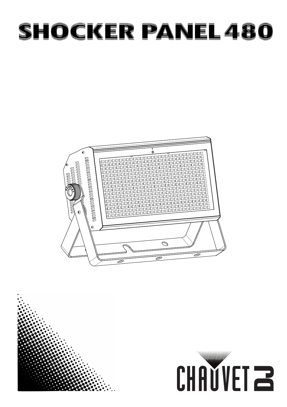
• Quick Reference Guide
Unpacking
Instructions
Carefully unpack the product immediately and check the container to make sure al
l the
parts are in the package and are in good condition.
Claims
If the box or the contents (the product and included accessories) appear damaged from
shipping, or show signs of mishandling, notify the carrier immediately, not Chauvet. Failure
to report damage to the carrier immediately may invalidate your claim. In addition, keep the
box and contents for inspection.
For other issues, such as missing components or parts, damage not related to shipping, or
concealed damage, file a claim with Chauvet within 7 days of delivery.
Text
Conventions
Convention Meaning
1— 512
A range of values
50/60
A set of values of which only one can be chosen
Settings
A menu option not to be modified
Menu > Settings
A sequence of menu options to be followed
<ENTER>
A key to be pressed on the product’s control panel
ON
A value to be entered or selected
Symbols
Symbol Meaning
Electrical warning. Not following these instructions may cause
electrical damage to the product, accessories, or the user.
Critical installation, configuration, or operation information. Not
following these instructions may make the product not work, cause
damage to the product, or cause harm to the operator.
Important installation or configuration information. The product
may not function correctly if this information is not used.
Useful information.
Disclaimer
The information and specifications contained in this document are subject to change
without notice. Chauvet assumes no responsibility or liability for any errors o
r omissions
that may appear in this manual. Chauvet
reserves the right to update the existing
document or to create a new document to correct any errors or omissions.
You can download the latest version of this document from www.chauvetlighting.com.
© Copyright 2015 Chauvet. All rights reserved.
Electronically published by Chauvet in the United States of America.
Author Updated Editor Date
R. Isenstadt 05/08/15 M. Trouard 07/09/15


Product specificaties

Merk: Chauvet
Categorie: Effect machine
Model: Shocker Panel 480

Heb je hulp nodig?

Als je hulp nodig hebt met Chauvet Shocker Panel 480 stel dan hieronder een vraag en andere gebruikers zullen je antwoorden


Handleiding Effect machine Chauvet

Handleiding Effect machine

Nieuwste handleidingen voor Effect machine