Chacon 34949 Handleiding
Chacon Alarmsysteem 34949
Bekijk gratis de handleiding van Chacon 34949 (56 pagina’s), behorend tot de categorie Alarmsysteem. Deze gids werd als nuttig beoordeeld door 13 mensen en kreeg gemiddeld 4.4 sterren uit 7 reviews. Heb je een vraag over Chacon 34949 of wil je andere gebruikers van dit product iets vragen? Stel een vraag
Pagina 1/56
USER GUIDE
For 34949
EN
www.chacon.be
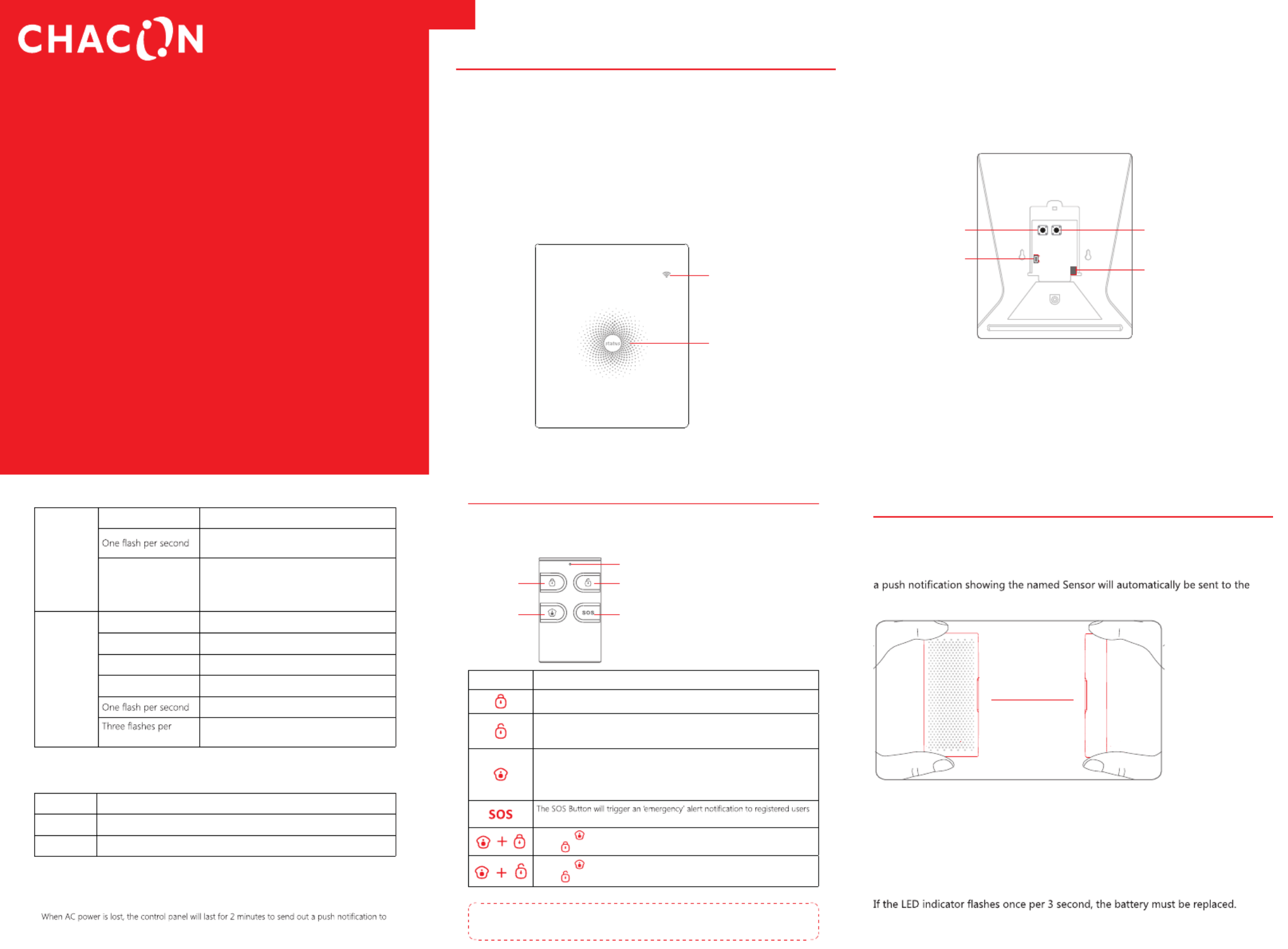
Control Panel
All Sensors are wirelessly linked to the Control Panel.
In the event of alarm activation, for example, when a Sensor is triggered, a push
notification will automatically be sent to all registered users.
The sysem can be conted and montrollitored both on-sie us ng the tiRemote Control
supplied and remotely from anywhere in the world, with the FREE iOS and Android
Apps.
The system can easily be expanded to include up to: 50 Wireless Sensors and 10
Remote Controls.
WiFi Indicator
Status Indicator
Network Configuration
Por Swiwetch
Power Adapter Jack
Learn Button
LED Indication
WiFi Indicator
(Blue)
Steady OnConnected with Router
Searching for a network or disconnected
from Router
Off
1) Initialization (the Control Panel beeps every
3 seconds): lasts for up to 30 seconds after
power up
2) The Power Adapter is not plugged in
Status
Indicator
(Red, Blue
and Green)
Steady OnStable WiFi connection
RedSystem is Armed
Blue System is in Home Mode (Part Arm)
GreenSystem is Disarmed
Disconnected from the Router
second Alarm condition
Functionality of Buttons behind the Back Cover
LearnUsed to pair an accessory with the Control Panel
WiFi Used to pair the Control Panel with the Router
On/offPower Switch
Note: The Control Panel must be plugged in to the Power Adapter in order to maintain the WiFi
connection.
the connected smartphones, and the sounder will keep beeping for 30 seconds.
Remote Control
The Remote Control can be used to arm, part arm or disarm the system, and trigger
an emergency alarm (SOS).
SOS Button
Arm Disarm
Status Indicator
Home Arm
(Part Arm)
ButtonSystem Status
A Sers br henhprllnso wille Amed. This m fodise or use w te opis unoupierty cced.
The System will be Disarmed, no Sensors will be triggered.
Note: When set to ‘Disarm’, Fire, Smoke, and Gas Leakage Sensors will remain
active as they are factory set to ‘24 Hour Zone’
Sensors which are set to the Home Zone will not be Armed. All other Sensors
will be Armed. This mode allows for selected Sensors (for example, front/back
door(s) to be Armed, allowing the occupier freedom of movement within the
property.
regardless of the Control Panel mode.
Press the button. After the indicator on the remote control blinks once, [ ]
press [ ] button within 3 seconds to mutely arm the system.
Press the button. After the indicator on the Remote Control blinks once, [ ]
press [ ] button within 3 seconds to mutely disarm the system.
Note: To turn off the Arm/Disarm tone permanently, open the AW1 Alarm App, go to ‘Internal
Siren'.
Door/ Window Sensor
D/ Ssor stNormal Z’lrilroting oorWindow eniset o ‘one by defau t and ae dea for pect
entry/exit points such as front and back doors and windows. When the system is
Armed, should a Sensor be triggered (Magnet separated from the Transmitter),
registered users and the Control Panel Internal Siren will sound immediately.
Alarming
when 1cm>
LED blinks once
Tamper Switch
The Tamper Switch (small black button underneath the back cover) will activate an
alarm condition if an unauthorized attempt is made to remove the Sensor from its
installed location.
Low Battery Indication
Product specificaties
| Merk: | Chacon |
| Categorie: | Alarmsysteem |
| Model: | 34949 |
Heb je hulp nodig?
Als je hulp nodig hebt met Chacon 34949 stel dan hieronder een vraag en andere gebruikers zullen je antwoorden
Handleiding Alarmsysteem Chacon

17 Juni 2023
19 Mei 2023
3 Mei 2023
1 Mei 2023
28 April 2023
7 April 2023
1 April 2023
23 Maart 2023
11 Maart 2023
11 Maart 2023
Handleiding Alarmsysteem
Nieuwste handleidingen voor Alarmsysteem
27 Mei 2026
5 Mei 2026
4 April 2026
2 April 2026
2 April 2026
1 April 2026
1 April 2026
10 Maart 2026
10 Maart 2026
9 Maart 2026