Carrier NSA-3PCT-RH Handleiding
Carrier Meetapparatuur NSA-3PCT-RH
Bekijk gratis de handleiding van Carrier NSA-3PCT-RH (9 pagina’s), behorend tot de categorie Meetapparatuur. Deze gids werd als nuttig beoordeeld door 38 mensen en kreeg gemiddeld 4.5 sterren uit 6 reviews. Heb je een vraag over Carrier NSA-3PCT-RH of wil je andere gebruikers van dit product iets vragen? Stel een vraag
Pagina 1/9
RH Wall Plate Thermistor
Installation and Operation
#NSA-HH/RH3-CP-SP-010-C, NSA-HH/RH2-CP-SP-010-C – 11/14/2019
Specifications subject to change without notice.
Catalog No. 11-808-779-01 Page 1 of 9
Overview
The Carrier Relative Humidity with Thermistor Wall Plate Series utilizes a thermoset
polymer capacitive sensing element with a factory applied hygroscopic filter to deliver a
proportional analog voltage output signal. The hygroscopic filter provides added
resistance to moisture, dust, and other chemicals for greater long term reliability. The
RH Stainless Plate transmitter features integral DIP switches for field selection of the
proper output signal and supply voltage to meet your applications requirements. Each
unit also contains 0%, 50%, and 100% test options to verify that the transmitter is both
working and properly installed. Field calibration can be performed by using the
increment and decrement calibration DIP switches without the need to replace the
sensing element. These enhancements provide increased flexibility and outstanding
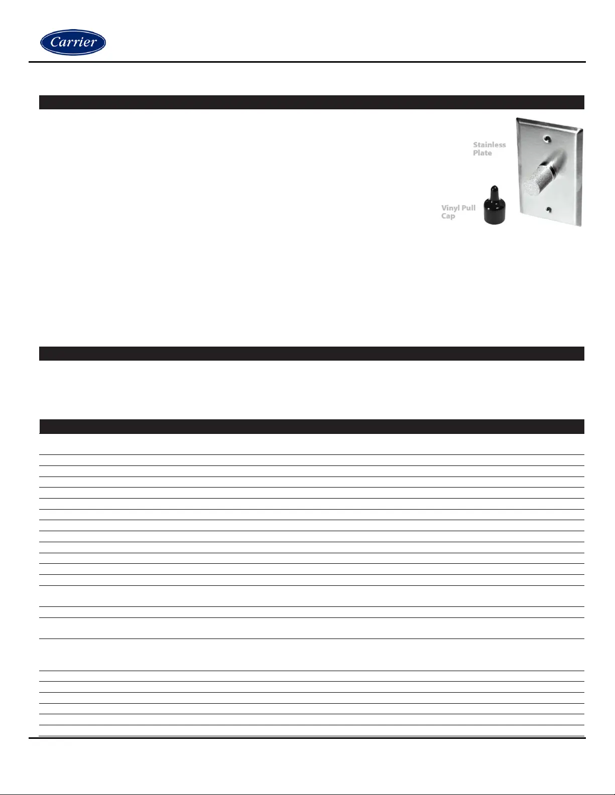
long-term reliability. All RH Stainless Plate transmitters come standard with an attractive brushed finish stainless steel,
single gang wall mounting plate and are designed to mount over a single gang junction box in the wall. The PCBs are
conformally coated for added protection from moisture and other contaminants. A temporary plastic sensor cover is
included to provide protection for the RH sensor from chemicals used in wash down applications.
Applications: Pharmaceutical, Hospitals, Operating Rooms, Vivariums, Clean Rooms, Process Control, Wash Down
Environments & Stability Chambers
Part Numbers
NSA-HH/RH3-CP-SP-010-C NSA-HH/RH2-CP-SP-010-C
Specifications
RH Supply Voltage
(Reverse Polarity Protected):
0-5 VDC: 12 - 40 VDC / 18 - 28 VAC
0-10 VDC: 18 - 40 VDC / 18 - 28 VAC
RH Supply Current (VA):
8 mA maximum (0.32 VA)
RH Output Load Resistance:
4K Ohms Minimum
RH Output Signal:
3-wire: 0-5 or 0-10 VDC
RH Accuracy @ 77°F (25°C):
+/- 2%, 3%, or 5% from 10 to 95%
RH Measurement Range:
0-100%
Operating RH Range:
0 to 95% RH, non-condensing (Conformally Coated PCB’s)
Operating Temperature Range:
-40 to 140°F (-40 to 60°C)
Storage Temperature Range:
-40 to 149°F (-40 to 65°C)
RH Stability | Repeatability | Sensitivity:
Less than 2% drift / 5 years | 0.5% RH | 0.1% RH
RH Response Time (T63):
20 Seconds Typical
RH Sensor Type:
Capacitive with Hydrophobic Filter
RH Transmitter Stabilization Time:
30 Minutes (Recommended time before doing accuracy verification)
RH Connections | Wire Size:
Screw Terminal Blocks (Polarity Sensitive) | 16 (1.31 mm²) to 26 AWG (0.129
mm²)
RH Terminal Block Torque Rating:
4.43 to 5.31 lb-in (0.5 to 0.6 Nm)
RH NIST Test Points:
Default Test Points: 3 Points (20%, 50% & 80%) or 5 Points (20%, 35%, 50%,
65% & 80%)
Nominal Thermistor Resistive Output @ 77°F
(25°C) (Lead Wire Colors), Non-Linear NTC
(Negative Temperature Coefficient):
10KΩ (White/Green)
Thermistor Accuracy 32-158°F (0-70°C):
+/- 0.36°F (0.2°C)
Thermistor Power Dissipation Constant:
3 mW/°C
Thermistor Sensor Response Time (T63):
10 Seconds nominal
Lead Wire Length | Conductor Size:
14” (35.6 cm) | 22 AWG (0.65 mm)
Insulation | Rating:
Etched Teflon (PTFE) Colored Leads | Mil Spec 16878/4 Type E
Wall Plate Material:
430 Stainless Steel (Brushed Stainless Steel Finish)
Product specificaties
| Merk: | Carrier |
| Categorie: | Meetapparatuur |
| Model: | NSA-3PCT-RH |
Heb je hulp nodig?
Als je hulp nodig hebt met Carrier NSA-3PCT-RH stel dan hieronder een vraag en andere gebruikers zullen je antwoorden
Handleiding Meetapparatuur Carrier

10 Januari 2024
Handleiding Meetapparatuur
Nieuwste handleidingen voor Meetapparatuur
21 Juli 2026
21 Juli 2026
20 Juli 2026
20 Juli 2026
18 Juli 2026
17 Juli 2026
17 Juli 2026
17 Juli 2026
17 Juli 2026
16 Juli 2026