Camille Bauer Sineax Si815-5 Handleiding
Camille Bauer Meetapparatuur Sineax Si815-5
Bekijk gratis de handleiding van Camille Bauer Sineax Si815-5 (4 pagina’s), behorend tot de categorie Meetapparatuur. Deze gids werd als nuttig beoordeeld door 55 mensen en kreeg gemiddeld 4.0 sterren uit 9 reviews. Heb je een vraag over Camille Bauer Sineax Si815-5 of wil je andere gebruikers van dit product iets vragen? Stel een vraag
Pagina 1/4
1
Passive
DC signal isolator
SINEAX SI 815-5
SI 815-5 Be 974 180-02 10.10
Camille Bauer Ltd.
Aargauerstrasse 7
CH-5610 Wohlen/Switzerland
Phone +41 56 618 21 11
Fax +41 56 618 35 35
info@camillebauer.com
www.camillebauer.com
Operating Instructions
3. Brief description
The signal isolator SINEAX SI 815-5 serves to electrically insulate
the 4...20 mA input circuit of a two-wire transmitter. It performs two
tasks at the same time. Firstly it provides electrical insulation and
secondly it conducts the power supply needed for measurement to
the two-wire transmitter without injecting into the circuit itself. Thus
the isolator does not require an power supply connection itself.
Some versions of the SINEAX SI 815-5 are designed for FSK com-
munication. They are used in conjunction with “intelligent” two-wire
transmitter which are capable of dialogue and operation according
to the FSK principle and the HART or user-specifi c protocol.
The series also includes “intrinsically safe” versions [EEx ia] IIC with
an intrinsically safe measurement/supply circuit. These operate in
conjunction with intrinsically safe two-wire transmitters located in
explosion hazard areas.
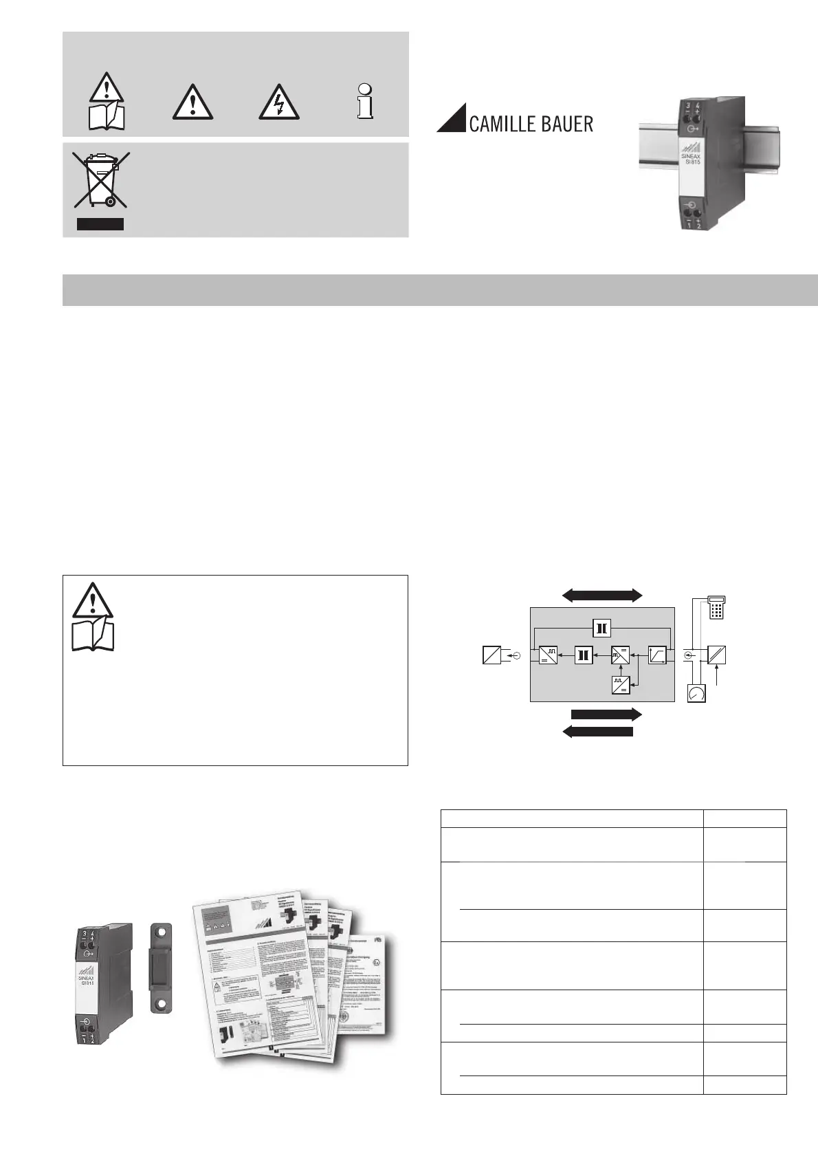
O
TZG
A
LR
X
mA
E
2-wire
transducer
+
–
+
–
4...20 mA
W
Digital signal
Power supply
Analog signal
Power pack
Power
supply
Receiver
4...20 mA
Hand-held
terminal
FSK
Fig. 3. Block diagram.
4. Specifi cation and ordering information
Order Code815 - 5 . 1 . .
1.Mechanical design
Housing N175
2.Version
Standard (non-Ex)
Output signal non-intrinsically safe 1
[EEx ia] IIC,
Output signal intrinsically safe 2
3.Number of isolation and
transmission channels
1 channel (interface) 1
4.Field communications protocol
Without FSK communication 0
With FSK communication 1
5.Climatic rating
Standard climatic rating 0
Improved climatic rating 1
The following symbols in the Operating Instructions indicate safety
precautions which must be strictly observed:
The instruments must only be disposed of in the
correct way!
Contents
1. Read fi rst and then … .............................................................1
2. Scope of supply .......................................................................1
3. Brief description .......................................................................1
4. Specifi cation and ordering information ....................................1
5. Technical data ..........................................................................2
6. Mounting ..................................................................................2
7. Electrical connections ..............................................................3
8. Commissioning and maintenance ...........................................4
9. Releasing the signal isolator ....................................................4
10. Dimensional drawings ..............................................................4
11. Declaration of conformity ........................................................4
1. Read fi rst and then …
The proper and safe operation of the device assumes
that the Operating Instructions are read carefully and
the safety warnings given in the sections
6. Mounting
7. Electrical connections
are observed.
The device should only be handled by appropriately
trained personnel who are familiar with it and author-
ised to work in electrical installations.
Unauthorized repair or alteration of the unit invalidates
the warranty.
2. Scope of supply
Signal isolator (Fig. 1)
1 Adapter (Fig. 1) for wall mounting
1 Operating Instructions (Fig. 2) in English, French, German
1 Ex approval (Fig. 2), only for Ex version devices
Fig. 1 Fig. 2
Product specificaties
| Merk: | Camille Bauer |
| Categorie: | Meetapparatuur |
| Model: | Sineax Si815-5 |
Heb je hulp nodig?
Als je hulp nodig hebt met Camille Bauer Sineax Si815-5 stel dan hieronder een vraag en andere gebruikers zullen je antwoorden
Handleiding Meetapparatuur Camille Bauer

5 Februari 2025
4 Januari 2025
19 Maart 2024
19 Maart 2024
19 Maart 2024
19 Maart 2024
8 Februari 2024
8 Februari 2024
8 Februari 2024
8 Februari 2024
Handleiding Meetapparatuur
Nieuwste handleidingen voor Meetapparatuur
17 Juli 2026
17 Juli 2026
17 Juli 2026
17 Juli 2026
16 Juli 2026
16 Juli 2026
16 Juli 2026
16 Juli 2026
16 Juli 2026
16 Juli 2026