Broan BBN3306SSC Handleiding
Bekijk gratis de handleiding van Broan BBN3306SSC (63 pagina’s), behorend tot de categorie Afzuigkap. Deze gids werd als nuttig beoordeeld door 16 mensen en kreeg gemiddeld 4.7 sterren uit 3 reviews. Heb je een vraag over Broan BBN3306SSC of wil je andere gebruikers van dit product iets vragen? Stel een vraag
Pagina 1/63
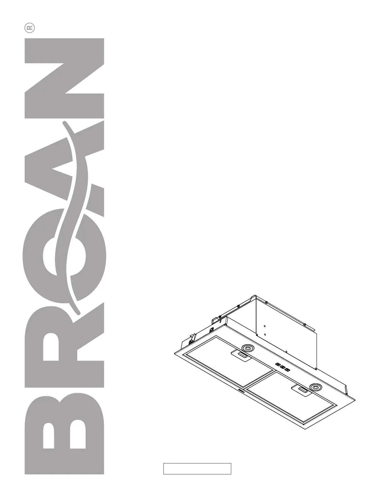
INSTALLATION,
USE & CARE INSTRUCTIONS
HB0385
WWW.BROAN-NUTONE.COMWWW.BROAN-NUTONE.CA
Serial number:
1105026D
Powerpack Inserts
Model numbers:
BBN3306SS, BBN3306SSC
Product specificaties
| Merk: | Broan |
| Categorie: | Afzuigkap |
| Model: | BBN3306SSC |
Heb je hulp nodig?
Als je hulp nodig hebt met Broan BBN3306SSC stel dan hieronder een vraag en andere gebruikers zullen je antwoorden
Handleiding Afzuigkap Broan

3 Maart 2026
5 Februari 2026
4 Februari 2026
4 Februari 2026
4 Februari 2026
3 Februari 2026
3 Februari 2026
3 Februari 2026
3 Februari 2026
3 Februari 2026
Handleiding Afzuigkap
Nieuwste handleidingen voor Afzuigkap
24 April 2026
23 April 2026
22 April 2026
22 April 2026
22 April 2026
22 April 2026
22 April 2026
21 April 2026
21 April 2026
21 April 2026