Bresser OMNI-4 Handleiding
Bresser Niet gecategoriseerd OMNI-4
Bekijk gratis de handleiding van Bresser OMNI-4 (4 pagina’s), behorend tot de categorie Niet gecategoriseerd. Deze gids werd als nuttig beoordeeld door 21 mensen en kreeg gemiddeld 5.0 sterren uit 7 reviews. Heb je een vraag over Bresser OMNI-4 of wil je andere gebruikers van dit product iets vragen? Stel een vraag
Pagina 1/4
OMNI-4
RED INVERTED REFLEX SIGHT INSTRUCTIONS
CAUTION: BEFORE YOU BEGIN, ENSURE THAT THE FIREARM IS CLEAR. REMOVE MAGAZINE,
LOCK ACTION OPEN AND VISUALLY INSPECT TO ENSURE THAT THE CHAMBER IS CLEAR.
PRODUCT SPECIFICATIONS
POWERING UP AND POWERING DOWN THE RED DOT
Depress and release the “+” or “-” button to power up the red dot; press “+” and “-” button to
power down the red dot. This red dot has a convenient auto-o feature that will switch o
the device if it has been left on for more than 4 hours. If the unit shuts down automatically,
moving or lifting the gun will turn the unit on again automatically. However, if the unit is
turned o by pressing “+” and “-” simultaneously, the unit will not be turned on automatically
by moving or lifting the gun.
ADJUSTING BRIGHTNESS
Pressing the power button repeatedly will step through 10 brightness settings. Select the
lowest brightness setting that still provides good contrast against the target; using too high
a setting may make the reticle appear distorted.
BATTERY
This red dot comes equipped with 3-volt lithium battery, NEDA type 2032. It is installed with
the positive side “+” down.
INSTALLATION
CAUTION:BEFORE YOU BEGIN, ENSURE THAT THE FIREARM IS CLEAR. REMOVE MAGAZINE,
LOCK ACTION OPEN AND VISUALLY INSPECT TO ENSURE THAT THE CHAMBER IS CLEAR.
To get the best performance from your red dot, it must be mounted properly. If you are not
familiar with mounting a red dot, it is strongly recommended that you seek the assistance of
a qualied professional.
MOUNT ONTO A PICATINNY OR WEAVERSTYLE RAIL
Your sight has integrated mounting rails that attach to a standard Weaver-style base
or Picatinny rail.
Loosen the mounting screw and set the sight onto the mounting base of the rearm. The
mounting screw should t into one of the grooves in the top of the mounting base. Be sure
the sight is fully seated on the mounting base before tightening the mounting screw.
( DO NOT OVER TIGHTEN MOUNTING HARDWARE. MAX. TORQUE 20 INCH LBS. )
For additional security, a drop of thread-locker can be added to the mounting screw.
ZEROING
Initial Setup
The dot position has been pre-set at the factory. Only minor windage and elevation
adjustments should be required. If possible, a bore sighting device should be used for rough
alignment of the sight to the rearm. If bore sighting is not possible, place the rearm on
a sturdy rest and look through the barrel or along the rail at a small target about 25 yards
away. Turn on the red dot and select a suitable brightness. Using a straight-slot screwdriver,
adjust the windage and elevation until the dot position corresponds with the target. Note
the following when making adjustments.
Click value: 1 MOA (approximately 1” at 100 yards; ¼” at 25 yards)
Windage: Counterclockwise (indicated by arrow) moves point of impact right/clockwise, left.
Elevation: Counterclockwise (indicated by arrow) moves point of impact up/clockwise, down.
FINAL SETUP (LIVE FIRE)
CAUTION:USE ADEQUATE EYE AND EAR PROTECTION AT ALL TIMES. SHOOT ONLY AT AN
APPROVED RANGE OR SUITABLE SAFE AREA.
CAUTION: IF YOU HAVE USED A BORE SIGHTER, CONFIRM THAT THE BORE SPUD IS NO
LONGER IN THE MUZZLE AND THAT THE BORE IS UNOBSTRUCTED.
Position the target no further than 25 yards away to begin the zeroing process. Turn on
the red dot and select a suitable brightness. Carefully re three shots and note where they
strike on the target. Your group should strike the target no greater than 10” from your point
of aim. (Should the group be farther away than this, the mounting process is faulty and
must be corrected before proceeding.) Make adjustments to windage and elevation so that
your group strikes the target approximately 1” beneath the point of aim with no windage
error (at six o’clock, neither left nor right).
When complete, position the target at the desired zero distance. Fire three rounds at this
distance and adjust as necessary to hit dead-on.
RETICLE
Your sight uses a 3 MOA reticle pattern. One MOA is about 1” at a distance of 100 yards (or
3/4” at 75 yards, 1/2” inch at 50 yards, etc.).
MIRROR ANGLE
The mirror-lens can be easily seen when looking through the wrong end of the sight. The tilt
of the mirror-lens is not a defect. It is tilted to reflect the LED’s light back to the user’s eye.
CAUTION: BEFORE YOU BEGIN, ENSURE THAT THE FIREARM IS CLEAR. REMOVE
MAGAZINE, LOCK ACTION OPEN AND VISUALLY INSPECT TO ENSURE THAT THE CHAMBER
IS CLEAR.
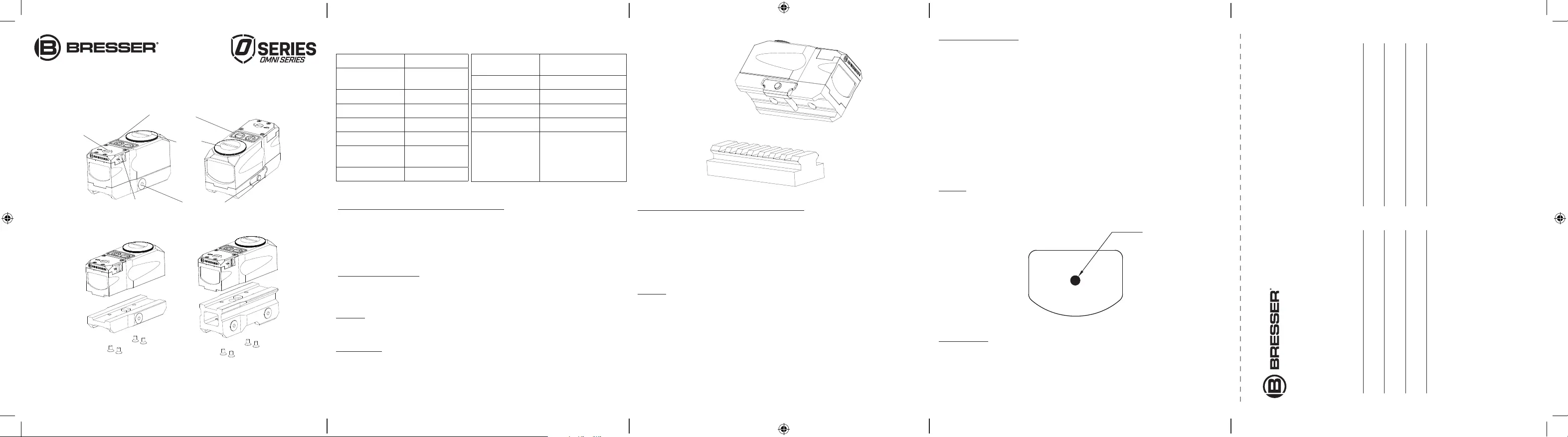
The OMNI-4 mini red dot sight may be mounted in two configuraons:
PRODUCT SPECIFICATIONS
Model OMNI-4
Descripon RED INVERTED REFLEX SIGHT
Magnificaon 1x
Length 3.0"
Width 1.3"
Height (low / high) 1.7" / 2.4"
Opcal height (low / high) 0.7" / 1.4"
Weight (low / high) 0.3 LBS / 0.36 LBS
Power Supply CR2032 3V Lithium Baery
Range of Adjustment
Windage 30 MOA
Elevaon 30 MOA
Click Value 1 MOA
Accessories
Picanny Mount
4 Mounng Screws
2mm Hex Wrench
3mm Hex Wrench
POWERING UP AND ADJUSTING DOT BRIGHTNESS
Powering Up and Powering Down the Red Dot
Depress and release the "+" or "-" buon to power up the red dot; press "+" and "-"
buon to power down the red dot. This red dot has a convenient auto-off feature that
will switch off the device if it has been le on for more than 4 hours. If the unit shuts
down automacally, moving or liing the gun will turn the unit on again automacally.
However, if the unit is turned off by pressing "+" and "-" simultaneously, the unit will not
be turned on automacally by moving or liing the gun.
Adjusng Brightness
Pressing the power buon repeatedly will step through 10 brightness sengs. Select the
lowest brightness seng that sll provides good contrast against the target; using too
high a seng may make the recle appear distorted.
Baery
This red dot comes equipped with 3-volt lithium baery, NEDA type 2032. It is installed
with the posive side “+” down.
INSTALLATION
CAUTION: BEFORE YOU BEGIN, ENSURE THAT THE FIREARM IS CLEAR. REMOVE
MAGAZINE, LOCK ACTION OPEN AND VISUALLY INSPECT TO ENSURE THAT THE CHAMBER
IS CLEAR.
To get the best performance from your red dot, it must be mounted properly. If you are
not familiar with mounng a red dot, it is strongly recommended that you seek the
assistance of a qualified professional.
Mount onto a Picanny or Weaver-style rail
Your sight has integrated mounng rails that aach to a standard Weaver-style base or
Picanny rail.
Loosen the mounng screw and set the sight onto the mounng base of the firearm. The
mounng screw should fit into one of the grooves in the top of the mounng base. Be
sure the sight is fully seated on the mounng base before ghtening the mounng screw.
(DO NOT OVER TIGHTEN MOUNTING HARDWARE. MAX. TORQUE 20 INCH LBS.) For
addional security, a drop of thread-locker can be added to the mounng screw.
ZEROING
Inial Setup
The dot posion has been pre-set at the factory. Only minor windage and elevaon
adjustments should be required. If possible, a bore sighng device should be used for
rough alignment of the sight to the firearm. If bore sighng is not possible, place the
firearm on a sturdy rest and look through the barrel or along the rail at a small target
about 25 yards away. Turn on the red dot and select a suitable brightness. Using a
straight-slot screwdriver, adjust the windage and elevaon unl the dot posion
corresponds with the target. Note the following when making adjustments.
Click value: 1 MOA (approximately 1" at 100 yards; ¼” at 25 yards)
Windage: Counterclockwise (indicated by arrow) moves point of impact right/clockwise,
le.
Elevaon: Counterclockwise (indicated by arrow) moves point of impact up/clockwise,
down.
Final Setup (Live Fire)
CAUTION: USE ADEQUATE EYE AND EAR PROTECTION AT ALL TIMES. SHOOT ONLY AT AN
APPROVED RANGE OR SUITABLE SAFE AREA.
CAUTION: IF YOU HAVE USED A BORE SIGHTER, CONFIRM THAT THE BORE SPUD IS NO
LONGER IN THE MUZZLE AND THAT THE BORE IS UNOBSTRUCTED.
Posion the target no further than 25 yardsaway to begin the zeroing process. Turn on
the red dotand select a suitable brightness. Carefullyfirethree shotsand notewhere
they strike on the target. Your group should strike the target no greater than 10" from
your point of aim. (Should the group be farther away than this, the mounng process is
faulty and must be corrected before proceeding.) Make adjustments to windage and
elevaon so that your group strikes the target approximately1" beneath the point of aim
with no windage error (at six o’clock, neither le nor right).
When complete, posion the target at the desired zero distance. Fire three roundsat this
distance and adjust as necessary to hit dead-on.
RETICLE
Your sight uses a 3 MOArecle paern.
One MOA is about1” at a distance of 100 yards(or 3/4”at 75 yards, 1/2” inch at 50 yards,
etc.).
MIRROR ANGLE
The mirror-lens can be easily seen when looking through the wrong end of the sight. The
lt of the mirror-lens is nota defect. It islted to reflect the LED’s light backto the user’s
eye.
MAINTENANCE & CLEANING
Although your red dotis extremelydurable, it is a precision instrument that should be
treated with reasonable care.
Lenses
The opcal coangs are hard and will last indefinitely with propercare.
Should either protecve windows become dirty, blow loose materials offbefore cleaning.
Use lens cleaning fluid and a so cloth to dab at the surfaceand remove any abrasive bits
of dust and dirt beforeapplying morepressure. Bepaent and clean in steps so as to not
grind abrasive dirt into the lens.
Exterior
Should the exterior become dirty,it may be cleaned with a damp cloth.Do not use oil or
solvents as they may be harmful ifinadvertently rubbed onto the opcal coangs.
STORAGE
This red dot has been constructed using adhesives and lubricants that enable a broad
range of operaonal and storage environments. The grease used is temperature-stable
from -50 to +175 degrees Fahrenheit.Do not store at temperatures outside this range
(for examplea car trunk on a veryhot day).
TROUBLESHOOTING
Please use the following guide to test/correct operaonal issues with thisred dot.
1. Red dot will not power up.
A. Checkto see that the baery isproperly installed with “+” side facing down.
B. Replacebaery.
C.Inspect baeryterminals for corrosion or debrisinhibing contact and correct as
necessary.
D. Should the above be ineffecve in resolving the problem,contact Bresser (add
appropriate contact info here) for return procedures.
2. Red dot brightness willnotadjust.
A. Move to where ambient light is low enough to clearly discern a change in brightness.
B. Follow fault diagnosis#1A-C above and repeat 2A. If brightness will notadjust,contact
Bresser (add appropriate contact info here) for return procedures.
3. Red dot will not zero.
Review seconsof thismanual regarding zeroing.Thisred dotis pre-centered at the
factory; ifmore than 10" of adjustment is required at a sight-in distance of 25 yards,
mounng is at fault.
4.Red dot will not adjust for windage and/or elevaon
Thisred dothas a maximum adjustment range of 30 MOA. Beyond this range of
adjustment,rotang the W/E screws will not provide addional point of impact change.
If you believe that your red dot iswithin the maximum range of adjustment and not
providing W/E movement, contact Bresser (add appropriate contact info here) for return
procedures.
5. Red dot appearance and/or target isnot clear.
A. Besureto select the lowest brightness seng that sll provides good contrast against
the target; using too high a seng may make the recle appear distorted.
B. Inspect both sides of the main lens for contaminaon and clean as necessary. (See
MAINTENANCE & CLEANING in this manual.)
C.Inspect the protecve window in front of the diode and clean as necessary. (See
MAINTENANCE & CLEANING in this manual.)
D. Should the above be ineffecve in resolving the problem,contact Bresser ( add
appropriate contact info here ) ( for return procedures.
LIFETIME LIMITED WARRANTY
JOC warranty.
3 MOA
Elevaon Adjustment
Windage Adjustment
Power/Brightness
Control
Baery
Compartment
Mounng Screw
CAUTION: BEFORE YOU BEGIN, ENSURE THAT THE FIREARM IS CLEAR. REMOVE
MAGAZINE, LOCK ACTION OPEN AND VISUALLY INSPECT TO ENSURE THAT THE CHAMBER
IS CLEAR.
The OMNI-4 mini red dot sight may be mounted in two configuraons:
PRODUCT SPECIFICATIONS
Model OMNI-4
Descripon RED INVERTED REFLEX SIGHT
Magnificaon 1x
Length 3.0"
Width 1.3"
Height (low / high) 1.7" / 2.4"
Opcal height (low / high) 0.7" / 1.4"
Weight (low / high) 0.3 LBS / 0.36 LBS
Power Supply CR2032 3V Lithium Baery
Range of Adjustment
Windage 30 MOA
Elevaon 30 MOA
Click Value 1 MOA
Accessories
Picanny Mount
4 Mounng Screws
2mm Hex Wrench
3mm Hex Wrench
POWERING UP AND ADJUSTING DOT BRIGHTNESS
Powering Up and Powering Down the Red Dot
Depress and release the "+" or "-" buon to power up the red dot; press "+" and "-"
buon to power down the red dot. This red dot has a convenient auto-off feature that
will switch off the device if it has been le on for more than 4 hours. If the unit shuts
down automacally, moving or liing the gun will turn the unit on again automacally.
However, if the unit is turned off by pressing "+" and "-" simultaneously, the unit will not
be turned on automacally by moving or liing the gun.
Adjusng Brightness
Pressing the power buon repeatedly will step through 10 brightness sengs. Select the
lowest brightness seng that sll provides good contrast against the target; using too
high a seng may make the recle appear distorted.
Baery
This red dot comes equipped with 3-volt lithium baery, NEDA type 2032. It is installed
with the posive side “+” down.
INSTALLATION
CAUTION: BEFORE YOU BEGIN, ENSURE THAT THE FIREARM IS CLEAR. REMOVE
MAGAZINE, LOCK ACTION OPEN AND VISUALLY INSPECT TO ENSURE THAT THE CHAMBER
IS CLEAR.
To get the best performance from your red dot, it must be mounted properly. If you are
not familiar with mounng a red dot, it is strongly recommended that you seek the
assistance of a qualified professional.
Mount onto a Picanny or Weaver-style rail
Your sight has integrated mounng rails that aach to a standard Weaver-style base or
Picanny rail.
Loosen the mounng screw and set the sight onto the mounng base of the firearm. The
mounng screw should fit into one of the grooves in the top of the mounng base. Be
sure the sight is fully seated on the mounng base before ghtening the mounng screw.
(DO NOT OVER TIGHTEN MOUNTING HARDWARE. MAX. TORQUE 20 INCH LBS.) For
addional security, a drop of thread-locker can be added to the mounng screw.
ZEROING
Inial Setup
The dot posion has been pre-set at the factory. Only minor windage and elevaon
adjustments should be required. If possible, a bore sighng device should be used for
rough alignment of the sight to the firearm. If bore sighng is not possible, place the
firearm on a sturdy rest and look through the barrel or along the rail at a small target
about 25 yards away. Turn on the red dot and select a suitable brightness. Using a
straight-slot screwdriver, adjust the windage and elevaon unl the dot posion
corresponds with the target. Note the following when making adjustments.
Click value: 1 MOA (approximately 1" at 100 yards; ¼” at 25 yards)
Windage: Counterclockwise (indicated by arrow) moves point of impact right/clockwise,
le.
Elevaon: Counterclockwise (indicated by arrow) moves point of impact up/clockwise,
down.
Final Setup (Live Fire)
CAUTION: USE ADEQUATE EYE AND EAR PROTECTION AT ALL TIMES. SHOOT ONLY AT AN
APPROVED RANGE OR SUITABLE SAFE AREA.
CAUTION: IF YOU HAVE USED A BORE SIGHTER, CONFIRM THAT THE BORE SPUD IS NO
LONGER IN THE MUZZLE AND THAT THE BORE IS UNOBSTRUCTED.
Posion the target no further than 25 yardsaway to begin the zeroing process. Turn on
the red dotand select a suitable brightness. Carefullyfirethree shotsand notewhere
they strike on the target. Your group should strike the target no greater than 10" from
your point of aim. (Should the group be farther away than this, the mounng process is
faulty and must be corrected before proceeding.) Make adjustments to windage and
elevaon so that your group strikes the target approximately1" beneath the point of aim
with no windage error (at six o’clock, neither le nor right).
When complete, posion the target at the desired zero distance. Fire three roundsat this
distance and adjust as necessary to hit dead-on.
RETICLE
Your sight uses a 3 MOArecle paern.
One MOA is about1” at a distance of 100 yards(or 3/4”at 75 yards, 1/2” inch at 50 yards,
etc.).
MIRROR ANGLE
The mirror-lens can be easily seen when looking through the wrong end of the sight. The
lt of the mirror-lens is nota defect. It islted to reflect the LED’s light backto the user’s
eye.
MAINTENANCE & CLEANING
Although your red dotis extremelydurable, it is a precision instrument that should be
treated with reasonable care.
Lenses
The opcal coangs are hard and will last indefinitely with propercare.
Should either protecve windows become dirty, blow loose materials offbefore cleaning.
Use lens cleaning fluid and a so cloth to dab at the surfaceand remove any abrasive bits
of dust and dirt beforeapplying morepressure. Bepaent and clean in steps so as to not
grind abrasive dirt into the lens.
Exterior
Should the exterior become dirty,it may be cleaned with a damp cloth.Do not use oil or
solvents as they may be harmful ifinadvertently rubbed onto the opcal coangs.
STORAGE
This red dot has been constructed using adhesives and lubricants that enable a broad
range of operaonal and storage environments. The grease used is temperature-stable
from -50 to +175 degrees Fahrenheit.Do not store at temperatures outside this range
(for examplea car trunk on a veryhot day).
TROUBLESHOOTING
Please use the following guide to test/correct operaonal issues with thisred dot.
1. Red dot will not power up.
A. Checkto see that the baery isproperly installed with “+” side facing down.
B. Replacebaery.
C.Inspect baeryterminals for corrosion or debrisinhibing contact and correct as
necessary.
D. Should the above be ineffecve in resolving the problem,contact Bresser (add
appropriate contact info here) for return procedures.
2. Red dot brightness willnotadjust.
A. Move to where ambient light is low enough to clearly discern a change in brightness.
B. Follow fault diagnosis#1A-C above and repeat 2A. If brightness will notadjust,contact
Bresser (add appropriate contact info here) for return procedures.
3. Red dot will not zero.
Review seconsof thismanual regarding zeroing.Thisred dotis pre-centered at the
factory; ifmore than 10" of adjustment is required at a sight-in distance of 25 yards,
mounng is at fault.
4.Red dot will not adjust for windage and/or elevaon
Thisred dothas a maximum adjustment range of 30 MOA. Beyond this range of
adjustment,rotang the W/E screws will not provide addional point of impact change.
If you believe that your red dot iswithin the maximum range of adjustment and not
providing W/E movement, contact Bresser (add appropriate contact info here) for return
procedures.
5. Red dot appearance and/or target isnot clear.
A. Besureto select the lowest brightness seng that sll provides good contrast against
the target; using too high a seng may make the recle appear distorted.
B. Inspect both sides of the main lens for contaminaon and clean as necessary. (See
MAINTENANCE & CLEANING in this manual.)
C.Inspect the protecve window in front of the diode and clean as necessary. (See
MAINTENANCE & CLEANING in this manual.)
D. Should the above be ineffecve in resolving the problem,contact Bresser ( add
appropriate contact info here ) ( for return procedures.
LIFETIME LIMITED WARRANTY
JOC warranty.
3 MOA
Elevaon Adjustment
Windage Adjustment
Power/Brightness
Control
Baery
Compartment
Mounng Screw
Model23-20400
DescriptionRed Inverted
Reflex Sight
Magnication1x
Length3.0”
Width1.3”
Height (low/high)1.7”/2.4”
Optical Height
(low/high)
0.7”/1.4”
Weight (low/high)0.3lbs/0.36lbs
Power SupplyCR2032 3V
Lithium Battery
Brightness1 - 11
Windage30 MOA
Elevation30 MOA
Click Value1 MOA
AccessoriesPicatinny Mount
4 Mounting Screws
2mm Hex Wrench
3mm Hex Wrench
CAUTION: BEFORE YOU BEGIN, ENSURE THAT THE FIREARM IS CLEAR. REMOVE
MAGAZINE, LOCK ACTION OPEN AND VISUALLY INSPECT TO ENSURE THAT THE CHAMBER
IS CLEAR.
The OMNI-4 mini red dot sight may be mounted in two configuraons:
PRODUCT SPECIFICATIONS
Model OMNI-4
Descripon RED INVERTED REFLEX SIGHT
Magnificaon 1x
Length 3.0"
Width 1.3"
Height (low / high) 1.7" / 2.4"
Opcal height (low / high) 0.7" / 1.4"
Weight (low / high) 0.3 LBS / 0.36 LBS
Power Supply CR2032 3V Lithium Baery
Range of Adjustment
Windage 30 MOA
Elevaon 30 MOA
Click Value 1 MOA
Accessories
Picanny Mount
4 Mounng Screws
2mm Hex Wrench
3mm Hex Wrench
POWERING UP AND ADJUSTING DOT BRIGHTNESS
Powering Up and Powering Down the Red Dot
Depress and release the "+" or "-" buon to power up the red dot; press "+" and "-"
buon to power down the red dot. This red dot has a convenient auto-off feature that
will switch off the device if it has been le on for more than 4 hours. If the unit shuts
down automacally, moving or liing the gun will turn the unit on again automacally.
However, if the unit is turned off by pressing "+" and "-" simultaneously, the unit will not
be turned on automacally by moving or liing the gun.
Adjusng Brightness
Pressing the power buon repeatedly will step through 10 brightness sengs. Select the
lowest brightness seng that sll provides good contrast against the target; using too
high a seng may make the recle appear distorted.
Baery
This red dot comes equipped with 3-volt lithium baery, NEDA type 2032. It is installed
with the posive side “+” down.
INSTALLATION
CAUTION: BEFORE YOU BEGIN, ENSURE THAT THE FIREARM IS CLEAR. REMOVE
MAGAZINE, LOCK ACTION OPEN AND VISUALLY INSPECT TO ENSURE THAT THE CHAMBER
IS CLEAR.
To get the best performance from your red dot, it must be mounted properly. If you are
not familiar with mounng a red dot, it is strongly recommended that you seek the
assistance of a qualified professional.
Mount onto a Picanny or Weaver-style rail
Your sight has integrated mounng rails that aach to a standard Weaver-style base or
Picanny rail.
Loosen the mounng screw and set the sight onto the mounng base of the firearm. The
mounng screw should fit into one of the grooves in the top of the mounng base. Be
sure the sight is fully seated on the mounng base before ghtening the mounng screw.
(DO NOT OVER TIGHTEN MOUNTING HARDWARE. MAX. TORQUE 20 INCH LBS.) For
addional security, a drop of thread-locker can be added to the mounng screw.
ZEROING
Inial Setup
The dot posion has been pre-set at the factory. Only minor windage and elevaon
adjustments should be required. If possible, a bore sighng device should be used for
rough alignment of the sight to the firearm. If bore sighng is not possible, place the
firearm on a sturdy rest and look through the barrel or along the rail at a small target
about 25 yards away. Turn on the red dot and select a suitable brightness. Using a
straight-slot screwdriver, adjust the windage and elevaon unl the dot posion
corresponds with the target. Note the following when making adjustments.
Click value: 1 MOA (approximately 1" at 100 yards; ¼” at 25 yards)
Windage: Counterclockwise (indicated by arrow) moves point of impact right/clockwise,
le.
Elevaon: Counterclockwise (indicated by arrow) moves point of impact up/clockwise,
down.
Final Setup (Live Fire)
CAUTION: USE ADEQUATE EYE AND EAR PROTECTION AT ALL TIMES. SHOOT ONLY AT AN
APPROVED RANGE OR SUITABLE SAFE AREA.
CAUTION: IF YOU HAVE USED A BORE SIGHTER, CONFIRM THAT THE BORE SPUD IS NO
LONGER IN THE MUZZLE AND THAT THE BORE IS UNOBSTRUCTED.
Posion the target no further than 25 yardsaway to begin the zeroing process. Turn on
the red dotand select a suitable brightness. Carefullyfirethree shotsand notewhere
they strike on the target. Your group should strike the target no greater than 10" from
your point of aim. (Should the group be farther away than this, the mounng process is
faulty and must be corrected before proceeding.) Make adjustments to windage and
elevaon so that your group strikes the target approximately1" beneath the point of aim
with no windage error (at six o’clock, neither le nor right).
When complete, posion the target at the desired zero distance. Fire three roundsat this
distance and adjust as necessary to hit dead-on.
RETICLE
Your sight uses a 3 MOArecle paern.
One MOA is about1” at a distance of 100 yards(or 3/4”at 75 yards, 1/2” inch at 50 yards,
etc.).
MIRROR ANGLE
The mirror-lens can be easily seen when looking through the wrong end of the sight. The
lt of the mirror-lens is nota defect. It islted to reflect the LED’s light backto the user’s
eye.
MAINTENANCE & CLEANING
Although your red dotis extremelydurable, it is a precision instrument that should be
treated with reasonable care.
Lenses
The opcal coangs are hard and will last indefinitely with propercare.
Should either protecve windows become dirty, blow loose materials offbefore cleaning.
Use lens cleaning fluid and a so cloth to dab at the surfaceand remove any abrasive bits
of dust and dirt beforeapplying morepressure. Bepaent and clean in steps so as to not
grind abrasive dirt into the lens.
Exterior
Should the exterior become dirty,it may be cleaned with a damp cloth.Do not use oil or
solvents as they may be harmful ifinadvertently rubbed onto the opcal coangs.
STORAGE
This red dot has been constructed using adhesives and lubricants that enable a broad
range of operaonal and storage environments. The grease used is temperature-stable
from -50 to +175 degrees Fahrenheit.Do not store at temperatures outside this range
(for examplea car trunk on a veryhot day).
TROUBLESHOOTING
Please use the following guide to test/correct operaonal issues with thisred dot.
1. Red dot will not power up.
A. Checkto see that the baery isproperly installed with “+” side facing down.
B. Replacebaery.
C.Inspect baeryterminals for corrosion or debrisinhibing contact and correct as
necessary.
D. Should the above be ineffecve in resolving the problem,contact Bresser (add
appropriate contact info here) for return procedures.
2. Red dot brightness willnotadjust.
A. Move to where ambient light is low enough to clearly discern a change in brightness.
B. Follow fault diagnosis#1A-C above and repeat 2A. If brightness will notadjust,contact
Bresser (add appropriate contact info here) for return procedures.
3. Red dot will not zero.
Review seconsof thismanual regarding zeroing.Thisred dotis pre-centered at the
factory; ifmore than 10" of adjustment is required at a sight-in distance of 25 yards,
mounng is at fault.
4.Red dot will not adjust for windage and/or elevaon
Thisred dothas a maximum adjustment range of 30 MOA. Beyond this range of
adjustment,rotang the W/E screws will not provide addional point of impact change.
If you believe that your red dot iswithin the maximum range of adjustment and not
providing W/E movement, contact Bresser (add appropriate contact info here) for return
procedures.
5. Red dot appearance and/or target isnot clear.
A. Besureto select the lowest brightness seng that sll provides good contrast against
the target; using too high a seng may make the recle appear distorted.
B. Inspect both sides of the main lens for contaminaon and clean as necessary. (See
MAINTENANCE & CLEANING in this manual.)
C.Inspect the protecve window in front of the diode and clean as necessary. (See
MAINTENANCE & CLEANING in this manual.)
D. Should the above be ineffecve in resolving the problem,contact Bresser ( add
appropriate contact info here ) ( for return procedures.
LIFETIME LIMITED WARRANTY
JOC warranty.
3 MOA
Elevaon Adjustment
Windage Adjustment
Power/Brightness
Control
Baery
Compartment
Mounng Screw
Continue on back
Cut and mail in
Register your product.
Learn about the full range of service your warranty provides.
Registering online is quick and easy!
https://explorescientificusa.com/product-registration
For products that do not include a serial number, use the product item number followed by the date of purchase
expressed in a six-digit format. For example, a purchase date of January 1, 2018, would be entered as 010118.
Model numbers:
Serial numbers:
The OMNI-4 red dot sight may be mounted in two congurations:
LOW PROFILE MOUNTHIGH CO-WITNESS MOUNT
FOLDFOLDFOLDFOLD4.25 IN
5.5 IN
Product specificaties
| Merk: | Bresser |
| Categorie: | Niet gecategoriseerd |
| Model: | OMNI-4 |
Heb je hulp nodig?
Als je hulp nodig hebt met Bresser OMNI-4 stel dan hieronder een vraag en andere gebruikers zullen je antwoorden
Handleiding Niet gecategoriseerd Bresser

5 Februari 2026
21 Januari 2026
7 November 2025
23 Juni 2024
20 September 2023
12 September 2023
14 Mei 2023
27 April 2023
27 April 2023
22 April 2023
Handleiding Niet gecategoriseerd
Nieuwste handleidingen voor Niet gecategoriseerd
23 Juli 2026
23 Juli 2026
23 Juli 2026
23 Juli 2026
23 Juli 2026
23 Juli 2026
23 Juli 2026
23 Juli 2026
23 Juli 2026
22 Juli 2026