Benning Tritest Control Handleiding

Benning Meetinstrumenten Tritest Control

Lees hieronder de 📖 handleiding in het Nederlandse voor Benning Tritest Control (20 pagina's) in de categorie Meetinstrumenten. Deze handleiding was nuttig voor 30 personen en werd door 2 gebruikers gemiddeld met 4.5 sterren beoordeeld

Pagina 1/20
BENNING
BENNING
BENNINGBENNING
BENNING
BENNING
L1
L2
L3
TRITEST
Âź
control
Benning Elektrotechnik & Elektronik GmbH & Co. KG
MĂŒnsterstraße 135 - 137
D - 46397 Bocholt
Phone: +49 (0) 2871 - 93 - 0 ‱ Fax: +49 (0) 2871 - 93 - 429
www.benning.de ‱ E-Mail: duspol@benning.de
T.-Nr. 705826.01/ 03-2010

3
2
9
8
7
6
5
4
J
D Bedienungsanleitung
 Operating manual
F Mode d‘emploi
E
Manuel de instrucciones

РъĐșĐŸĐČĐŸĐŽŃŃ‚ĐČĐŸ Đ·Đ° Đ”ĐșŃĐżĐ»ĐŸĐ°Ń‚Đ°Ń†ĐžŃ
îȘ NĂĄvod k pouĆŸitĂ­ zkouĆĄečky
 KÀyttöohje
îș ÎŸÎŽÎ·ÎłÎŻÎ”Ï‚ Ï‡ÏÎźÏƒÎ”Ï‰Ï‚
H Kezelési utasítås
I Istruzioni per l’uso
 Naudojimosi instrukcija
N Bruksanvisning
 Gebruiksaanwijzing
P Manual de instrucÔes
 Instrukcja obsƂugi
 Instrucƣiuni de utilizare

Đ˜ĐœŃŃ‚Ń€ŃƒĐșцоя ĐżĐŸ эĐșŃĐżĐ»ŃƒĐ°Ń‚Đ°Ń†ĐžĐž
S Bruksanvisning
 Dutest aletinin kullanma
tarifnamesi
 Priručnik za upotrebu
D
Bedienungsanleitung
TRITESTÂź control
Der Drehfeldrichtungsanzeiger TRITEST
Âź control ist
ein MessgerĂ€t zum PrĂŒfen der Drehfeldrichtung (Pha-
senfolge) in 3-Phasen Drehstromnetzen (Untervertei-
lungen, Steckdosen usw.). Der anwendbare 3-Phasen
Nennspannungsbereich betrÀgt 400 V - 690 V, 50 Hz -
60 Hz. Als ErgÀnzungseinrichtung ist im MessgerÀt eine
batteriegespeiste LED-Taschenlampe integriert. Bevor
Sie das MessgerÀt benutzen, lesen Sie unbedingt diese
Bedienungsanleitung und beachten Sie die Sicherheits-
hinweise!
Inhaltsverzeichnis
1. Benutzerhinweise
2. Sicherheitshinweise
3. Lieferumfang
4. Funktionsbeschreibung des Drehfeldrich-
tungsanzeigers
5. Batterieeinbau/ Batterieanzeige
6. So prĂŒfen Sie die Drehfeldrichtung (Phasen-
folge)
7. Taschenlampenfunktion
8. Technische Daten
9. Instandhaltung/ Wartung
10. Umweltschutz
1. Benutzerhinweise
Diese Bedienungsanleitung richtet sich an
- ElektrofachkrÀfte und
- elektrotechnisch unterwiesene Personen
Der TRITESTÂź control ist zur PrĂŒfung in trockener
Umgebung vorgesehen und darf nicht in Drehstrom-
netzen mit einer höheren Nennspannung als 690 V
AC eingesetzt werden (siehe auch Abschnitt 9 „Tech-
nische Daten“).
In der Bedienungsanleitung und auf dem TRITEST
Âź
control werden folgende Symbole verwendet:
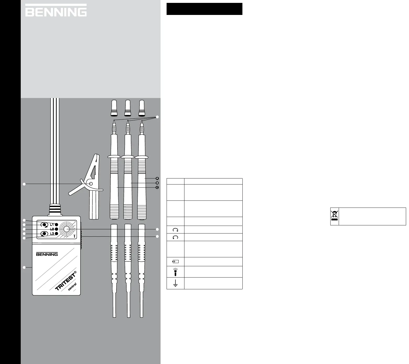
Symbol Bedeutung

Warnung vor elektrischer Gefahr!
Steht vor Hinweisen, die beachtet
werden mĂŒssen, um Gefahren fĂŒr
Menschen zu vermeiden.

Achtung Dokumentation beachten!
Das Symbol gibt an, dass Hinweise in
der Bedienungsanleitung zu beachten
sind, um Gefahren zu vermeiden.
DurchgĂ€ngige doppelte oder verstĂ€rkte
Isolierung (Schutzklasse II)
Rechtsdrehsinn, Rechtsdrehfeld
Linksdrehsinn, Linksdrehfeld
L1
L2
L3
Anschlussbezeichnungen an den
Anschluss-/ PrĂŒfleitungen; Phasen-
LED, signalisieren Spannung an L1,
L2, L3
Dieses Symbol zeigt die Ausrichtung der
Batterien zum polrichtigen Einlegen an
Symbol fĂŒr Taschenlampenfunktion
Erde (Spannung gegen Erde)
2. Sicherheitshinweise
- Das GerĂ€t ist gemĂ€ĂŸ DIN EN 61557-7/
VDE 0413-7, DIN EN 61557-1/ VDE 0413-1
gebaut und geprĂŒft und hat das Werk in einem
sicherheitstechnisch einwandfreien Zustand
verlassen. Um diesen Zustand zu erhalten und
einen gefahrlosen Betrieb sicherzustellen, muss
der Anwender die Hinweise und Warnvermerke
beachten, die in dieser Bedienungsanleitung ent-
halten sind.
- GerĂ€t beim PrĂŒfen nur an den isolierten PrĂŒfgrif-
fen , A B und C anfassen und die PrĂŒfelektroden
(PrĂŒfspitzen)  nicht berĂŒhren!
- Vor dem Öffnen des GehĂ€usedeckels
4 (Batterie-
fach) sind die PrĂŒfgriffe und von allen A, B C
Spannungsquellen und Messkreisen zu trennen!
Falls das GerÀt lÀngere Zeit nicht gebraucht wird,
Batterien aus dem GerÀt entfernen!
Verbrauchte Batterien nicht wegwerfen, als Son-
dermĂŒll entsorgen!
- Beachten Sie, Arbeiten an spannungsfĂŒhrenden
Teilen und Anlagen sind grundsÀtzlich gefÀhrlich.
Bereits Spannungen ab 30 V AC und 60 V DC
können fĂŒr den Menschen lebensgefĂ€hrlich sein!
- ÜberprĂŒfen Sie vor jeder Messung Ihr GerĂ€t auf
BeschÀdigungen.
- Vermeiden Sie unbedingt ein Feucht- oder Nass-
werden des MessgerÀtes. Ebenso ist das GerÀt
vor Verunreinigung und BeschĂ€digungen zu schĂŒt-
zen!
- Vermeiden Sie eine Betauung des GerÀtes (Kon-
denswasserbildung). Diese tritt ein, wenn das
GerÀt aus einer kalten in eine warme Umge-
bung gebracht wird. Im Innern des GerÀtes wird
dadurch die Isolationsfestigkeit herabgesetzt und
es können Mess- und Isolationsfehler auftreten. In
diesem Fall das GerÀt ca. 1 Stunde bei höherer
Temperatur an geeigneter Stelle aufbewahren.
- Wenn anzunehmen ist, dass ein gefahrloser
Betrieb nicht mehr möglich ist, so ist das GerÀt
außer Betrieb zu setzen und gegen unabsichtli-
chen Betrieb zu sichern
- Es ist anzunehmen, dass ein gefahrloser Betrieb
nicht mehr möglich ist,
- wenn das GerÀt sichtbare BeschÀdigungen
aufweist (GehĂ€use, Kabel, PrĂŒfgriffe),
- wenn das GerÀt nicht mehr arbeitet,
- nach lĂ€ngerer Lagerung unter ungĂŒnstigen
VerhÀltnissen,
- nach schweren Transportbeanspruchungen.
3. Lieferumfang
Zum Lieferumfang des TRITEST
Ÿ control gehören:
3.1 ein StĂŒck TRITEST
Âź control mit festen
Anschlussleitungen, L1, L2, L3
3.2 ein StĂŒck Sicherheits-PrĂŒfspitze L1, braun
(Spitze Ø = 4 mm, TN 709266)
3.3 ein StĂŒck Sicherheits-PrĂŒfspitze L2, schwarz
(Spitze Ø = 4 mm, TN 709267)
3.4 ein StĂŒck Sicherheits-PrĂŒfspitze L3, grau
(Spitze Ø = 4 mm, TN 709268)
3.5 ein StĂŒck Sicherheits-Abgreifklemme, schwarz
(Buchse Ø = 4mm, TN 709269)
4. Funktionsbeschreibung des Drehfeldrich-
tungsanzeigers
Im Drehfeldrichtungsanzeiger TRITEST
Âź control sind
zwei Spannungsteilersysteme in Sternschaltung
integriert. Ein System signalisiert die Phasen-LED
(Anzeige der Phasenspannungen, L1 9, L2 7 und
L3 5). Das andere System (Kombination aus Wider-
stand und Kondensator) bewirkt in Verbindung mit
zwei LED 8 und 6 die Drehfeldrichtungsanzeige. Der
Kondensator (Blindwiderstand) bildet mit den Wider-
stÀnden (Wirkwiderstand) eine Phasenverschiebung
und liegt annÀhernd mit einem Drehfeld (Wanderfeld)
in Phase. Die entsprechende LED (Rechtsdrehfeld
8
oder Linksdrehfeld 6) erhÀlt die höhere Spannung
und wird aktiviert.
Hinweis:
Die PrĂŒfung der Drehfeldrichtung (Phasenfolge) ist
auch bei entnommenen oder leeren Batterien voll
funktionsfÀhig.
5. Batterieeinbau/ Batterieanzeige
Vor dem Öffnen des GehĂ€usedeckels
4 sind die PrĂŒf-
griffe , A B und C
von allen Spannungsquellen und
Messkreisen zu trennen.
Das Batteriefach befindet sich hinter dem GehÀu-
sedeckel 4 auf der RĂŒckseite des GerĂ€tes. In den
SeitenwĂ€nden sind Öffnungsschlitze zum Lösen
des Deckels. Hierzu einen Schlitzschraubendre-
her 5,5 mm verwenden und durch eine Drehbe-
wegung den Deckel ĂŒber den Rastpunkt hinweg
bewegen, dann kann der Deckel entfernt werden.
Batterien immer polrichtig einlegen, siehe Batteriesym-
bol!
Achten Sie beim Schließen, dass der Deckel richtig
einrastet und seitlich am GehÀuse kein Spalt zu sehen
ist.
Bei Batterieunterspannung lÀsst sich die Taschen-
lampe nicht in Betrieb nehmen, dann Batteriewechsel
vornehmen!
6.
So prĂŒfen Sie die Drehfeldrichtung (Phasenfolge)
Kontaktieren Sie die Anschlussleitungen (PrĂŒflei-
tungen) L1, L2, L3 mit dem zu prĂŒfenden Netz. Ver-
wenden Sie gegebenenfalls die PrĂŒfspitzen und A B,
C und die Abgreifklemme
J.
Eine Anzeige der Phasenspannungen erfolgt durch die
LED L1 9
, L2 7
und L3 5.
Je nach Anschluss wird die LED fĂŒr „Rechtsdrehfeld“
8 oder „Linksdrehfeld“ 6 aktiviert. Bei jeder PrĂŒfung
ist auf das Vorhandensein aller drei Phasenspannun-
gen zu achten, nur dann ist die Anzeige auswertbar!
7. Taschenlampenfunktion
Durch den seitlich im GerÀt integrierten Schiebeschal-
ter 3 kann die LED-Lampe 2 eingeschaltet werden.
Die Taschenlampenfunktion ist unabhÀngig vom Dreh-
feldrichtungsanzeige-System.
8. Technische Daten
- Vorschriften, Drehfeldrichtungsanzeiger:
DIN EN 61557-7/ VDE 0413-7, DIN EN 61557-1/
VDE 0413-1, Referenz DIN EN 61010-1
- Nennspannungsbereich: 3-Phasen Wechselstrom
400 V - 690 V
- Max. Spannung gegen Erde: 400 V
- Überspannungskategorie: III (IEC/ EN 61010-031)
- PrĂŒfstrom: ≀ 3,5 mA
- Nennfrequenzbereich: 50 Hz - 60 Hz
-
Kurvenform der Netzspannung:
Sinus
- EMV, Stör-Aussendung und -Festigkeit:
DIN VDE 0843-20, IEC/ EN 61326
- Arbeitstemperaturbereich: - 10 °C bis 50 °C
- Lagertemperaturbereich: - 25 °C bis 75 °C
- Feuchte: 80 % bis 31 °C, linear abnehmend,
40 % bis 50 °C, keine Betauung!
- Höhe ĂŒber NN: 2000 m
- Schutzklasse: 2 (IEC 60536)
- Schutzart: IP 30 (DIN VDE 0470-1 IEC/ EN 60529)
3 - erste Kennziffer: Schutz gegen Zugang zu gefÀhr-
lichen Teilen und Schutz gegen feste Fremdkörper,
> 2,5 mm Durchmesser
0 - zweite Kennziffer: Kein Wasserschutz
- Verschmutzungsgrad: II (IEC 60664)
- BatteriebestĂŒckung: 3 Mignon-Batterien 1,5 V (4,5 V,
70 g), (IEC/ DIN R6/ LR6)
-
Lampe, LED, Stromaufnahme:
25 mA bei 4,5 V Batterie-
spannung
- BeleuchtungsstÀrke: ca. 30 Lux in 50 cm Abstand
-
Gebrauchsdauer der Batterie:
ca. 100 h bei Alkali-Mangan-Batterien
- Abmessung: 97 x 59 x 30 mm (ohne PrĂŒfkabel)
- Gewicht: ca. 320 g mit Messzubehör und Batterie
- PrĂŒfkabellĂ€nge: ca. 1000 mm
9. Instandhaltung/ Wartung
Zum Reinigen des GerÀtes verwenden Sie ein mit mil-
dem SpĂŒlmittel angefeuchtetes Tuch. Falls Elektrolyt-
verunreinigungen oder weiße Ablagerungen im Bereich
der Batterie oder des Batteriefaches vorhanden sind,
reinigen Sie diese mit einem trockenen Tuch.
Entfernen Sie bei lÀngerer Lagerung die Batterien aus
dem GerÀt!
Falls die LED-Lampe 2 nicht mehr leuchtet oder
schwach wird, so sind die Batterien durch neue zu
ersetzen.
10. Umweltschutz
Bitte fĂŒhren Sie das GerĂ€t am Ende seiner
Lebensdauer den zur VerfĂŒgung ste hen den
RĂŒckgabe- und Sammelsystemen zu.
BENNING
BENNING
BENNINGBENNING
BENNING
BENNING
L1
L2
L3
TRITEST
Âź
control
Benning Elektrotechnik & Elektronik GmbH & Co. KG
MĂŒnsterstraße 135 - 137
D - 46397 Bocholt
Phone: +49 (0) 2871 - 93 - 0 ‱ Fax: +49 (0) 2871 - 93 - 429
www.benning.de ‱ E-Mail: duspol@benning.de
T.-Nr. 705826.01/ 03-2010

3
2
9
8
7
6
5
4
J
D Bedienungsanleitung
 Operating manual
F Mode d‘emploi
E
Manuel de instrucciones

РъĐșĐŸĐČĐŸĐŽŃŃ‚ĐČĐŸ Đ·Đ° Đ”ĐșŃĐżĐ»ĐŸĐ°Ń‚Đ°Ń†ĐžŃ
îȘ NĂĄvod k pouĆŸitĂ­ zkouĆĄečky
 KÀyttöohje
îș ÎŸÎŽÎ·ÎłÎŻÎ”Ï‚ Ï‡ÏÎźÏƒÎ”Ï‰Ï‚
H Kezelési utasítås
I Istruzioni per l’uso
 Naudojimosi instrukcija
N Bruksanvisning
 Gebruiksaanwijzing
P Manual de instrucÔes
 Instrukcja obsƂugi
 Instrucƣiuni de utilizare

Đ˜ĐœŃŃ‚Ń€ŃƒĐșцоя ĐżĐŸ эĐșŃĐżĐ»ŃƒĐ°Ń‚Đ°Ń†ĐžĐž
S Bruksanvisning
 Dutest aletinin kullanma
tarifnamesi
 Priručnik za upotrebu

Operating manual
TRITESTÂź control
The phase-sequence indicator TRITEST
Âź control is a
measuring instrument for testing the phase sequence
of three-phase mains (subdistributions, sockets etc.).
The applicable three-phase nominal voltage range
is 400 V - 690 V, 50 Hz - 60 Hz. As supplementary
device, the measuring instrument is equipped with an
integrated battery-powered LED pocket lamp. Before
using the measuring instrument, carefully read this
operating manual and always observe the safety
instructions!
List of contents
1. Considerations for use
2. Safety instructions
3. Scope of delivery
4. Functional description of the phase-sequence
indicator
5. Battery installation/ battery indication
6. How to test the phase sequence
7. Pocket lamp function
8. Technical data
9. Maintenance
10. Environmental notice
1. Considerations for use
This operating manual is addressed to
- professional electricians and
- electrotechnically trained people.
The TRITESTÂź control is intended for being used in
dry ambient conditions and must not be used for three-
phase mains with a nominal voltage higher than 690 V
AC (also see section 9 „Technical data“).
The following symbols are used in this operating
manual and on the TRITESTÂź control:
symbol meaning

Warning of electric danger!
Indicates instructions that must be
observed in order to prevent danger for
people.

Attention! Observe documentation!
This symbol indicates that there are
instructions in the operating manual that
must be observed to prevent dangers.
Continuous double or reinforced insula-
tion (protection class II)
Phase sequence clockwise
Phase sequence anti-clockwise
L1
L2
L3
Connecting marks on the connecting/
test cables; phase LEDs signalling
voltage at L1, L2, L3
This symbol indicates the alignment
of the batteries for being inserted with
correct polarity.
Symbol for pocket lamp function
Ground (voltage to ground)
2. Safety instructions
- The device is designed and tested according to
DIN EN 61557-7/ VDE 0413-7, DIN EN 61557-1/
VDE 0413-1 and left our works in technically
safe condition. To preserve this condition and to
ensure safe operation, the user has to observe
all instructions and warnings contained in this
operating manual.
- During testing, hold the device by the insulated
test handles and only and do not touch A B, C
the testing electrodes (probe tips)
!
- Before opening the housing cover 4 (battery
compartment), separate the test handles A, B
and C from all voltage sources and measuring
circuits!
- Remove the batteries, when you do not use the
device for a longer period of time!
- Do not dispose of used batteries via the household
rubbish! Dispose of those batteries via special
waste facilities!
- Please observe: Working on live parts and
systems is dangerous! Even voltages from 30 V
AC and 60 V DC onwards might involve life-
threatening dangers for people!
- Check the device for damages before each
measurement.
- Always protect the measuring instrument against
moisture or dampness. Furthermore, protect it
against contamination and damages!
- Protect the device against condensation water.
Condensation water might form, if the device is
brought from a cold into a warm environment.
Thus, the insulating power inside the device might
be reduced and measuring and insulating faults
might occur. In such a case, store the device in an
appropriate environment at a higher temperature
for approx. 1 hour.
- If it can be assumed that safe operation is no
longer possible, put the device out of operation
and secure it against unintended operation.
- Safe operation is assumed to be no longer
possible, if
- the device exhibits visible damages (housing,
cable, test handles),
- the device no longer works,
- the device has been stored under
unfavourable conditions for a longer period of
time,
- the device was exposed to mechanical stress
due to transport.
3. Scope of delivery
The scope of delivery of the TRITEST
Âź control consists
of:
3.1 one TRITEST
Âź control with fixed connecting
cables, L1, L2, L3
3.2 one safety probe tip L1, brown (tip Ø = 4 mm,
TN 709266)
3.3 one safety probe tip L2, black (tip Ø = 4 mm,
TN 709267)
3.4 one safety probe tip L3, grey (tip Ø = 4 mm,
TN 709268)
3.5 one safety alligator clip, black (jack Ø = 4mm,
TN 709269)
4. Functional description of the phase-sequence
indicator
The phase-sequence indicator TRITEST
Âź control is
equipped with two integrated voltage divider systems
with star connection. One of the systems indicates the
phase LED (indication of the phase voltages L1
9, L2
7, L3 5
). The other system (combined resistance and
capacitor) ensures the phase-sequence indication by
means of two LEDs
8 and
6. The capacitor (reactive
impedance) and the resistances (active resistance)
build up a phase shift and is almost in phase with a
rotary field (travelling wave). The respective LED
(clockwise 8 or anti-clockwise 6 phase sequence)
gets the higher voltage and is activated.
Note:
The phase sequence can be tested even with the
batteries being removed or empty.
5. Battery installation/ battery indication
Before opening the housing cover 4, separate the
test handles and from all voltage sources and A, B C
measuring circuits.
The battery compartment is behind the housing cover
4 at the back of the device. There are apertures on
the sides of the device to release the cover. For this
purpose, use a 5.5 mm slotted screwdriver by means
of which you can move the cover over the holding
notch with a rotary movement. Thus, the cover can be
removed.
Please ensure correct polarity when inserting the
batteries (see battery symbol)!
When closing the housing, make sure that the cover
locks into place correctly and that there is no gap on
the side of the housing.
In case of low battery voltage, the pocket lamp cannot
be operated. Please replace the batteries!
6. How to test the phase sequence
Contact the connecting cables (test cables) L1, L2,
L3 with the mains to be tested. If necessary, use the
probe tips , and and the alligator clip A B C J.
The phase voltages are indicated by means of the
LEDs L1
9, L2 7 und L3 5.
Depending on the connection, the LED for “clockwise
phase sequence” 8 or for „anti-clockwise phase
sequence” 6 is activated. Please observe for each
testing that all of the three phase voltages have to be
present to obtain a correct indication!
7. Pocket lamp function
The LED lamp 2 can be switched on via the sliding
switch 3
integrated into the side of the device. The
pocket lamp function can be operated independently
of the phase-sequence indicator system.
8. Technical data
- Regulations, phase-sequence indicator:
DIN EN 61557-7/ VDE 0413-7, DIN EN 61557-1/
VDE 0413-1, reference DIN EN 61010-1
- Nominal voltage range: 3-phase AC current
400 V - 690 V
- Max. voltage to ground: 400 V
- Over voltage category: III
(IEC/ EN 61010-031)
- Testing current: ≀ 3,5 mA
- Nominal frequency range: 50 Hz - 60 Hz
- Curve behaviour of mains voltage: sinusoidal
- EMC, resistance to interference:
DIN VDE 0843-20 IEC/ EN 61326
- Working temperature range: - 10 °C to 50 °C
- Storing temperature range: - 25 °C to 75 °C
- Humidity: 80 % to 31 °C, linearly decreasing, 40 %
to 50 °C, not condensing!
- Altitude above sea level: 2000 m
- Protection class:
2 (IEC 60536)
- Protection type: IP 30 (DIN VDE 0470-1 IEC/
EN 60529)
3 - first index: Protection against access to
dangerous parts and protection against solid
impurities of a diameter > 2.5 mm
0 - second index: No protection against water
- Degree of contamination:
II (IEC 60664)
- Batteries: 3 round cell batteries 1.5 V (4.5 V, 70 g),
(IEC/ DIN R6/ LR6)
- Lamp, LED, power consumption: 25 mA at 4.5 V
battery voltage
- Illumination: approx. 30 lux in a distance of 50 cm
- Usable life of the battery: approx. 100 h with alkali-
manganese batteries
- Dimensions: 97 x 59 x 30 mm (without testing
cable)
- Weight: approx. 320 g with measuring accessories
and battery
- Testing cable length: approx. 1000 mm
9. Maintenance
For cleaning the device, use a cloth which is moistened
with a mild cleaning agent. If there is electrolyte
contamination or white deposit near the battery ort p2-h
battery compartment, remove them with a dry cloth.
Remove the batteries from the device when not using
it for a longer period of time!
If the LED lamp 2 does not work any longer or
becomes weak, replace the batteries by new ones of
the same type.
10. Environmental notice
At the end of the product’s useful life, please
dispose of it at appropriate collection points
provided in your country.
BENNING
BENNING
BENNINGBENNING
BENNING
BENNING
L1
L2
L3
TRITEST
Âź
control
Benning Elektrotechnik & Elektronik GmbH & Co. KG
MĂŒnsterstraße 135 - 137
D - 46397 Bocholt
Phone: +49 (0) 2871 - 93 - 0 ‱ Fax: +49 (0) 2871 - 93 - 429
www.benning.de ‱ E-Mail: duspol@benning.de
T.-Nr. 705826.01/ 03-2010

3
2
9
8
7
6
5
4
J
D Bedienungsanleitung
 Operating manual
F Mode d‘emploi
E
Manuel de instrucciones

РъĐșĐŸĐČĐŸĐŽŃŃ‚ĐČĐŸ Đ·Đ° Đ”ĐșŃĐżĐ»ĐŸĐ°Ń‚Đ°Ń†ĐžŃ
îȘ NĂĄvod k pouĆŸitĂ­ zkouĆĄečky
 KÀyttöohje
îș ÎŸÎŽÎ·ÎłÎŻÎ”Ï‚ Ï‡ÏÎźÏƒÎ”Ï‰Ï‚
H Kezelési utasítås
I Istruzioni per l’uso
 Naudojimosi instrukcija
N Bruksanvisning
 Gebruiksaanwijzing
P Manual de instrucÔes
 Instrukcja obsƂugi
 Instrucƣiuni de utilizare

Đ˜ĐœŃŃ‚Ń€ŃƒĐșцоя ĐżĐŸ эĐșŃĐżĐ»ŃƒĐ°Ń‚Đ°Ń†ĐžĐž
S Bruksanvisning
 Dutest aletinin kullanma
tarifnamesi
 Priručnik za upotrebu
F
Mode d’emploi
TRITESTÂź control
L’indicateur d’ordre de phases TRITEST
Âź control est
un instrument de mesure pour tester l’ordre de phases
dans les réseaux triphasés (distributions secondaires,
prises de courant etc.). La plage de tension nominale
triphasée applicable est 400 V - 690 V, 50 Hz - 60 Hz.
Comme dispositif complĂ©mentaire, l’appareil dispose
d’une lampe de poche DEL Ă  piles intĂ©grĂ©e. Avant
d’utiliser l’instrument de mesure, lire attentivement le
mode d’emploi et respecter les consignes de sĂ©curitĂ© !
Table des matiĂšres
1. Indications pour l’usager
2. Consignes de sécurité
3. Étendue de la livraison
4. Description fonctionnelle de l’indicateur
d’ordre de phases
5. Insertion des piles/ affichage de piles
6. Test de l’ordre de phases
7. Lampe de poche
8. Caractéristiques techniques
9. Entretien
10. Information sur l’environnement
1. Indications pour l’usager
Ce mode d’emploi s’adresse aux
- électriciens expérimentés et au
- personnel ayant reçu des instructions
Ă©lectrotechniques.
Le TRITESTÂź control est prĂ©vu pour ĂȘtre utilisĂ© dans
un environnement sec et ne doit pas ĂȘtre utilisĂ© dans
les réseaux triphasés avec une tension nominale
supérieure à 690 V AC (voir aussi la section 9
„CaractĂ©ristiques techniques“).
Les symboles suivants sont utilisés dans ce mode
d’emploi et sur l’appareil TRITEST
Âź control :
symbole signification

Avertissement ! Danger Ă©lectrique!
Indique des notes qui doivent ĂȘtre
respectés afin de prévenir des dangers
pour les individus.

Attention ! Respecter la documentation !
Indique des notes dans ce mode
d’emploi qui doivent ĂȘtre respectĂ©s afin
d’éviter des dangers.
Isolation continue double ou renforcĂ©e
(classe de protection II)
Ordre de phases dans le sens horaire
Ordre de phases dans le sens
antihoraire
L1
L2
L3
Marques de raccordement aux lignes
de raccordement et de test; DEL de
phases signalant de la tension Ă  L1,
L2, L3
Ce symbole indique l’orientation des
piles afin de respecter la polarité
correcte lors de l‘insertion des piles.
Symbole pour la lampe de poche
Masse (tension par rapport Ă  la terre)
2. Consignes de sécurité
- L’appareil est conçu et testĂ© d‘aprĂšs DIN EN
61557-7/ VDE 0413-7, DIN EN 61557-1/ VDE
0413-1 et a quitté notre usine dans en bon état
en ce qui concerne la sécurité. Afin de préserver
cet état et de garantir un service sûr, respecter les
notes et avertissements indiqués dans ce mode
d’emploi.
- Ne tenir l’appareil que par les poignĂ©es de test
isolées , A B et C sans toucher les électrodes de
contact (pointes de test)
!
- Avant d’ouvrir le couvercle du boütier 4
(compartiment à piles), séparer les poignées de
test , A B et C de toutes sources de tension et
des circuits de mesure !
- Enlever les piles si l’appareil n’est pas utilisĂ© pour
une période prolongée !
- Ne pas jeter les piles épuisées ! Les éliminer en
tant que déchets spéciaux !
- Tenir compte du fait que travailler avec des
composantes sous tension est dangereux. DĂ©jĂ 
des tensions Ă  partir de 30 V AC et 60 V DC
peuvent constituer un danger de mort pour les
individus !
- ContrĂŽler l’appareil avant chaque test pour vĂ©rifier
qu’il n’est pas endommagĂ©.
- Tout contact de l’appareil avec l’humiditĂ© est Ă 
Ă©viter. ProtĂ©ger l’appareil contre les salissures et
contre l’endommagement !
- Eviter le contact de l’appareil avec de l’eau
de condensation. L’eau de condensation
apparaĂźt quand l’appareil vient d’ĂȘtre mis d’un
environnement froid dans un environnement
chaud. Ainsi, la stabilitĂ© d‘isolement Ă  l‘intĂ©rieur
de l‘appareil est rĂ©duite et des dĂ©fauts de mesure
et d’isolement peuvent se produire. Dans ce cas,
garder l’appareil pour 1 heure environ à une
température dans un endroit approprié.
- S’il est probable qu’une utilisation sans danger
n’est plus possible, l’appareil doit ĂȘtre mis
hors service et protégé contre toute utilisation
involontaire.
- Une utilisation sans danger n’est plus possible si :
- l’appareil prĂ©sente des dommages visibles
(boßtier, cùbles, poignées de test),
- l’appareil ne fonctionne plus,
- aprĂšs un long stockage dans des conditions
défavorables,
- l’appareil a Ă©tĂ© transportĂ© dans des conditions
défavorables.
3. Etendue de la livraison
La livraison du TRITEST
Âź control comporte:
3.1 1 piĂšce TRITESTÂź control avec lignes de
raccordement fixes, L1, L2, L3
3.2 1 piÚce pointe de test de sécurité L1, brun
(pointe Ø = 4 mm, TN 709266)
3.3 1 piÚce pointe de test de sécurité L2, noir
(pointe Ø = 4 mm, TN 709267)
3.4 1 piÚce pointe de test de sécurité L3, gris
(pointe Ø = 4 mm, TN 709268)
3.5 1 piÚce pince crocodile de sécurité, noir
(douille Ø = 4mm, TN 709269)
4. Description fonctionnelle de l’indicateur
d’ordre de phases
Deux systÚmes diviseurs de tension connectés
en Ă©toile sont intĂ©grĂ©s dans l’indicateur d’ordre de
phases TRITEST
Âź control. Un systĂšme signale la
DEL de phase (indication des tensions de phase L1
9, L2 7, L3 5), l’autre systùme (une combinaison
d’une rĂ©sistance et d’un condensateur) effectue
l’indication d’ordre de phases à l’aide de deux DEL
8
et 6. Le condensateur (réactance) et les résistances
(résistance active) établissent un décalage de phases
et est presque en phase avec un champ magnétique
rotatif (champ d’ondes progressives). La DEL
concernée (ordre de phases dans le sens horaire
8
ou antihoraire 6) reçoit la tension plus haute et est
activée.
Note:
Il est aussi possible de tester l’ordre de phases avec
des piles épuisées ou enlevées.
5. Insertion des piles/ affichage de piles
Avant d’ouvrir le couvercle du boütier
4, séparer les
poignées de test et de toutes sources de A, B C
tension et des circuits de mesure.
Le compartiment Ă  piles se trouve derriĂšre le couvercle
du boütier 4 à la face arriùre de l’appareil. Dans les
parois latérales se trouvent des fentes afin de pouvoir
enlever le couvercle. Utiliser un tournevis Ă  fente de
5,5 mm et le tourner pour mouvoir le couvercle par-
dessus le point d’arrĂȘt et l’enlever.
Insérer les piles dans le compartiment à piles toujours
en respectant la polarité (voir le symbole de piles
indiquant la bonne polarité) !
Lors de fermer le couvercle, veiller Ă  ce que le
couvercle s’encliquette et qu’il n’y ait pas de fentes
aux cĂŽtĂ©s de l’appareil.
En cas d‘une sous-tension des piles, la lampe de
poche ne peut ĂȘtre utilisĂ©e. Dans ce cas, Ă©changer
les piles !
6. Test de l’ordre de phases
Contacter les lignes de raccordement (lignes de test)
L1, L2, L3 avec le réseau à mesurer. Utiliser les
pointes de test et et la pince crocodile A, B C J,
si nécessaire.
Les tensions de phase sont indiquées par les DEL L1
9
, L2
7
, L3 5
.
En fonction du raccordement, la DEL pour l’ordre de
phases dans le sens horaire 8 ou antihoraire 6 est
activée. Veiller à la présence des trois tensions de
phase lors de chaque test pour garantir une Ă©valuation
correcte de l’indication !
7. Lampe de poche
La lampe de poche DEL 2 peut ĂȘtre allumĂ©e Ă 
l’aide de l’interrupteur 3 Ă  coulisse intĂ©grĂ© sur le
cĂŽtĂ© de l’appareil. La fonction de la lampe de poche
est indĂ©pendante du systĂšme indicateur d’ordre de
phases.
8. Caractéristiques techniques
- rĂ©glementations, indicateur d’ordre de phases:
DIN EN 61557-7/ VDE 0413-7,DIN EN 61557-1/
VDE 0413-1, référence DIN EN 61010-1
- gamme de tension nominale: courant alternatif
triphasé 400 V - 690 V
- tension max. par rapport Ă  la terre: 400 V
- catégorie de surtension: III
(IEC/ EN 61010-031)
- courant de test: ≀ 3,5 mA
- gamme de fréquence nominale: 50 Hz - 60 Hz
- forme de la courbe de la tension secteur:
sinusoĂŻdal
- compatibilité électromagnétique etc.:
DIN VDE 0843-20 IEC/ EN 61326
- gamme de la température de travail: -10 °C à 50 °C
-
gamme de la température de stockage: -25 °C à 75 °C
- humidité: 80 % à 31 °C, décroissant linéairement,
40 % à 50 °C, pas d’eau de condensation !
- altitude au-dessus de la mer: 2000 m
- classe de protection:
2 (IEC 60536)
- type de protection: IP 30 (DIN VDE 0470-1 IEC/
EN 60529)
IP 30 signifie: protection contre l’accùs aux
composants dangereux et protection contre les
impuretés solides > 2,5 mm de diamÚtre, (3 -
premier indice). Aucune protection contre l’eau, (0
– second indice).
- degré de contamination:
II (IEC 60664)
- piles: 3 piles rondes 1,5 V (4,5 V, 70 g), (IEC/ DIN
R6/ LR6)
- lampe, DEL, consommation de courant: 25 mA Ă 
4,5 V tension de batterie
- intensité lumineuse: env. 30 Lux à une distance de
50 cm
- durĂ©e d’utilisation des piles: env. 100 h pour les
piles alcali-manganĂšse
- dimensions: 97 x 59 x 30 mm (sans cĂąble de test)
- poids: env. 320 g avec accessoires et piles
- longueur du cĂąble de test: env. 1000 mm
9. Entretien
Nettoyer l’appareil Ă  l’aide d’un chiffon lĂ©gĂšrement
humidifiĂ© avec un produit doux pour la vaisselle. S‘il
y a de la contamination électrolytique ou des dépÎts
blancs autour des piles ou dans le compartiment Ă 
piles, les nettoyer avec un chiffon sec. Enlever les
piles de l’appareil quand l’appareil n’est pas utilisĂ©
pendant une longue durĂ©e ! Au cas oĂč la lampe DEL
2 ne fonctionne plus ou son intensité lumineuse est
réduite, remplacer les piles par des piles neuves du
mĂȘme type.
10. Information sur l’environnement
Une fois le produit en fin de vie, veuillez
le déposer dans un point de recyclage
approprié.


Product specificaties

Merk: Benning
Categorie: Meetinstrumenten
Model: Tritest Control

Heb je hulp nodig?

Als je hulp nodig hebt met Benning Tritest Control stel dan hieronder een vraag en andere gebruikers zullen je antwoorden


Handleiding Meetinstrumenten Benning

Handleiding Meetinstrumenten

Nieuwste handleidingen voor Meetinstrumenten