AMX NXA-AVB/ETHERNET Handleiding
AMX AV extender NXA-AVB/ETHERNET
Bekijk gratis de handleiding van AMX NXA-AVB/ETHERNET (2 pagina’s), behorend tot de categorie AV extender. Deze gids werd als nuttig beoordeeld door 121 mensen en kreeg gemiddeld 4.0 sterren uit 7 reviews. Heb je een vraag over AMX NXA-AVB/ETHERNET of wil je andere gebruikers van dit product iets vragen? Stel een vraag
Pagina 1/2
Quick Start Guide
NXA-AVB/ETHERNETModero
®
Ethernet/Video Breakout Box
Overview
The NXA-AVB/ETHERNET Breakout Box (FG2254-10) facilitates the installation
and distribution of video, data, and audio to Modero touch panels located up to
200 feet (60.96 m) from the AVB box. This unit accepts either Composite or
S-Video from standard video devices. FIG.1 shows the NXA-AVB/ETHERNET
Breakout Box.
For more detailed installation and operating instructions, refer to the specific
Modero touch panel instruction manual, available online at www.amx.com.
Specifications
NXA-AVB/ETHERNET Breakout Box
FIG.1 shows the front and rear connectors on the breakout box.
Note: The breakout box unit can be mounted on either a horizontal flat surface
or into an equipment rack (by removing the front screws and attaching it to an
AC-RK).
Note: The PSN power supply being used on the NXA-AVB/ETHERNET is
dependent on the power requirements of the target touch panel.
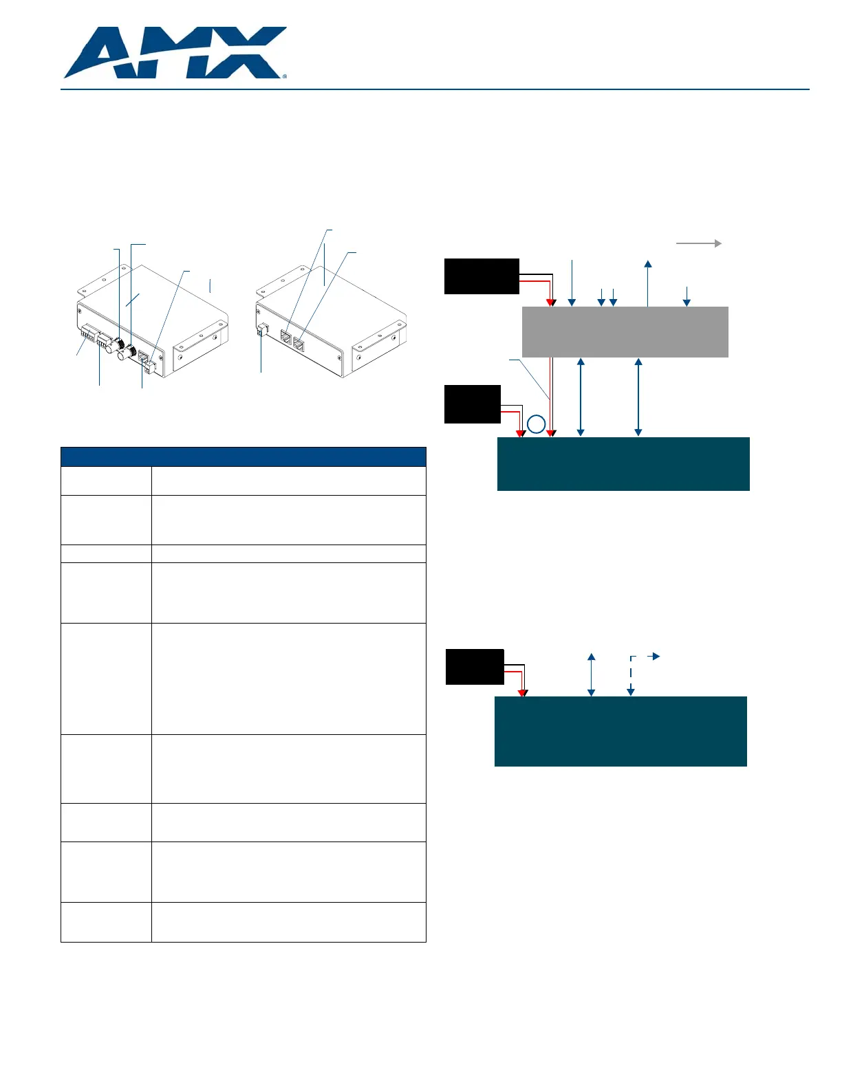
Connections and Wiring
A PSN power supply can indirectly provide power to a Modero panel by routing
power through the NXA-AVB/ETHERNET Breakout Box. FIG.2 shows a sample
wiring configuration using both an indirect or direct PSN power connection for a
video-capable Modero panel. Refer to the online Modero Touch Panel instruction
manuals for connection options.
The NXA-AVB/ETHERNET is an optional accessory for non-video capable
Modero touch panels but can only transfer Audio signals between the Breakout
Box and the target touch panel.
A PSN power supply can also directly provide power through the unit to a target
Modero panel. Refer to the specific Modero touch panel instruction manual for
detailed wiring information. FIG.3 shows a sample wiring configuration for a
non-video capable Modero panel.
Note:AMX recommends using the above power connection examples when
connecting the breakout box to your touch panel. If you want to attempt another
configuration or if you want to use two power supplies, be sure to avoid any
potential ground loops that may occur in your connection configuration. Ground
loops can cause display errors with your touch panel.
Wiring the NXA-AVB/ETHERNET connectors and cables
The inputs and outputs on the breakout box are separated into front and rear
connectors. The rear connectors are used to input external signals. The front
connectors are used to communicate signals between the
NXA-AVB/ETHERNET and a target Modero panel. FIG.4 provides a layout of
the wiring connection both into and from the breakout box.
FIG. 1 Connector layouts on the NXA-AVB/ETHERNET Breakout Box
NXA-AVB/ETHERNET Specifications
Dimensions
(HWD):
•1.50" x 5.55" x 4.88" (3.81 cm x 14.10 cm x 12.40 cm)
•Width when attached to mounting ears: 6.65" (16.89 cm)
Power
Consumption:
•50mA (with audio/video input)
•23mA (with no audio/video)
•Routed through AVB using a PSN power supply (Refer to
FIG.2 and FIG.3 for more information).
Certifications:•FCC, CE, and EN60950
Front Components:•2-pin 3.5 mm Phoenix connector for power to the touch panel
•Green LED provides an indication of power status
•RJ-45 connector provides Ethernet signals to the touch panel
•RJ-45 connector provides differential audio and video signals
to the touch panel (panel type dependent)
Rear Components:•6-pin 3.5 mm Phoenix connector for in-bound (left/right
channel) audio
•4-pin 3.5 mm Phoenix connector for out-bound (from
microphone) audio
•BNC connector (female) for Composite or Chroma
(for video-capable panels only)
•BNC connector (female) for luminance (for video-capable
panels only)
•RJ-45 connector for Ethernet input from the control system
•2-pin 3.5 mm Phoenix connector for in-bound power
Features:•Accepts either Composite or S-Video (video-capable
panels only)
•Provides audio distribution to the non-video touch panels
over a CAT5 cable (up to 200 ft.)
•Provides video/audio distribution to the video-capable touch
panels over CAT5 cable up to 200 ft. (60.9 m)
Availability:•This unit is not included with current Modero panels
•This unit is included with VG-series Video Kits and with the
7" panels
Included
Accessories:
•Two 2-pin Phoenix connectors (41-5025)
•One 4-pin Phoenix connector (41-5047)
•One 6-pin Phoenix connector (41-5063)
•One Rack Mount Kit (KA2250-40) with mounting bracket
(62-2254-02)
Optional
Accessories:
•AC-RK Accessory RackMount Kit (FG515)
•Modero Table Top Cable (CA2250-50)
•PSN6.5 power supply (FG423-41) (panel dependent)
Power
(front)
Ethernet (to panel)
Audio/Video
Power (to panel)
S-Video Chroma
Composite/
Mic Out
Audio
In
Ethernet
S-Video
Luma
(rear)
(to panel)
FIG. 2 Sample wiring configuration on video-capable panels using this Breakout Box
FIG. 3 Sample Wiring configuration on non-video panel using this Breakout Box
NXD/T Video-capable
Ethernet In
PSN power
(RJ-45)
Video In
(BNC)
Mic Out
(4-pin captive-wire)
Audio In
(6-pin captive-wire)
NXA-AVB/ETHERNET
PSN4.4/6.5
supplied via
NXA-AVB box
Audio/Video
(CAT5)
Line Level out
(to amplifier
or VOL card)
Touch Panels
or
Direct
Connect
Breakout Box
Ethernet
(rear)
(front)
(CAT5)
supply
Indirect
Connect
PSN power
supply
Direct
connect
NXD/T Non-video capable
Ethernet
(CAT5)
Touch Panels
PSN power
Audio (CAT5)
between optional
NXA-AVB/ETHERNET
Breakout Box
supply
Product specificaties
| Merk: | AMX |
| Categorie: | AV extender |
| Model: | NXA-AVB/ETHERNET |
| Kleur van het product: | Zwart |
| Soort: | AV-zender & ontvanger |
| Maximum resolutie: | - Pixels |
| Composiet video-ingang: | 1 |
| S-Video ingang: | 1 |
| Afmetingen (B x D x H): | 140.7 x 125.2 x 38.6 mm |
| Maximaal bereik: | 60.96 m |
| Ondersteundende kabel types: | Cat5 |
Heb je hulp nodig?
Als je hulp nodig hebt met AMX NXA-AVB/ETHERNET stel dan hieronder een vraag en andere gebruikers zullen je antwoorden
Handleiding AV extender AMX

13 November 2024
13 November 2024
13 November 2024
13 November 2024
13 November 2024
2 Februari 2024
14 November 2023
13 November 2023
13 November 2023
13 November 2023
Handleiding AV extender
Nieuwste handleidingen voor AV extender
23 Mei 2026
20 Mei 2026
18 Mei 2026
13 Mei 2026
12 Mei 2026
11 Mei 2026
4 Mei 2026
28 April 2026
20 April 2026
6 April 2026